The microfluidics revolution: manufacturing techniques and innovative applications
Writer
Celeste Chidiac, PhD
Keywords
Microfluidic Devices, Intelligent Microfluidics, Artificial Intelligence, Machine Learning
Author
Celeste Chidiac, PhD
Publication Date
Keywords
Paper microfluidics
3D printing
Organ-on-a-chip
Lab-on-a-chip
Droplet Microfluidics
Need advice for your manufacturing techniques?
Your microfluidic SME partner for Horizon Europe
We take care of microfluidic engineering, work on valorization and optimize the proposal with you
Find out about the recent advances in microfluidics manufacturing and applications and their vast impact on research, healthcare, and the development of science and technology.
Introduction
Microfluidics is the field that studies the behavior of fluid confined in a small volume, such as microchannels, droplets, etc., and exploits it for various research and industrial purposes. A small volume implies one with at least one dimension smaller than 1 mm. Most fluids’ behavior is unpredictable at this scale as the capillary and viscous forces that are primarily negligible in large scales become predominant in the small scale [1].
This review provides an overview of microfluidics technology, beginning with a brief history of its development, then exploring the key components of microfluidic devices and highlighting their main advantages. We discuss flow dynamics at the microscale to deepen the understanding of microfluidic device fabrication. Finally, we examine the current applications of microfluidics and consider its potential future uses.
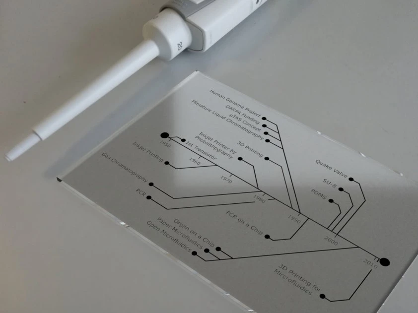
The history of microfluidics
Microfluidics arose from electrophoresis, the method of separating mixed-charged molecules by size and electrical charge using an electrical field [1]. The first microfluidic device was used as a platform to improve electrophoretic separation.
The simple definition of microfluidics is a thin sheet of fluid that can be fabricated using two glass plates and a spacer between them, and that is precisely how the first microfluidic devices were made for electrophoresis studies back in the 1940s [1].
Microelectronics was another parent of microfluidics; initially, researchers tried to adapt fabrication methods and materials from microelectronics to microfluidics. In 1964, the first integrated circuit was made by manufacturing resistors, capacitors, and transistors on the same piece of semiconductor material [2].
Molecular biology, especially genomics in the 1980s, strongly contributed to the evolution of microfluidics. Scientists’ interest in studying and sequencing nucleic acids led to developing sequencing machines capable of working with small samples to ensure a high-sensitivity read-out [3].
In the early 2000s, researchers realized that in vitro platforms were inadequate for exploring the physiological and inter-organ connections that occur in vivo. This led to the development of the first “human-on-a-chip” cell culture systems, aiming to miniaturize the body and study organ interactions and metabolism [4].
So why has microfluidics gained much popularity over the years?
Advantages of microfluidic devices
Microfluidics has several significant advantages that make it a unique science in research and industry [1]:
- Microfluidics can transfer entire laboratory operations into a single chip, providing several advantages, such as smaller reagent volumes, shorter reaction times, and parallel operation [5].
- The flow in microchannels is laminar, which allows mathematical calculations of flow patterns and, thus, makes quantitative predictions of the biological environment of cells and reagents. This deterministic behavior in microchannels is a unique property not found in the macroscopic world.
- Microfluidic channels can be fabricated on a cellular scale and used for probing, seeding, and sorting cells, which enables them to imitate physiological processes and parameters.
- Microvalves and micropumps can be integrated into a microfluidic device for a relatively low cost, enabling flow control and automation.
- Microfluidic devices have a much smaller footprint than their macrofluidic counterparts, occupying less space and being portable to resource-poor places.
- Microfluidics has a lower cost per unit regarding (batch) fabrication and operation, bringing great economic benefits. Thus, it is expected to allow high-throughput experiments.
Components of a microfluidic device
A microfluidic device may consist of channels, valves, pumps, mixers, filters, and heat exchangers. These parts allow dilution, particle separation, metering, flow switching, sample dispensing, or injection [5].
Valves and pumps are essential for microfluidic devices as they control fluid movement by regulating the flow rate. They can be integrated into a hybrid microfabricated device for different purposes. Using various materials in a chip can be beneficial because of the added values of each component, such as valves and pumps that can control the flow of multiple solutions in a microfluidic device [5].
Our experts have designed a starter pack for people who want an easy and accessible introduction to microfluidics. This microfluidic discovery kit provides everything you need to explore the field of precise fluid control.
Understanding fluid dynamics at the microscale is crucial to designing and fabricating microfluidic devices; the next section of the review will focus on flow dynamics in microfluidics.
Fluid dynamics at micro scale
The behavior of the fluid’s surface is different at the macro and micro scales. On the microscale, surface tension becomes dominant with respect to gravity (the dominant force at the macroscale) and can drive the fluid instead of a pump [6].
Capillary forces also begin to dominate gravitational forces as the dimensions of the system are reduced [6]. A capillary force is defined as a force applied to a fluid that drives it through the porous media or narrow capillary [6].
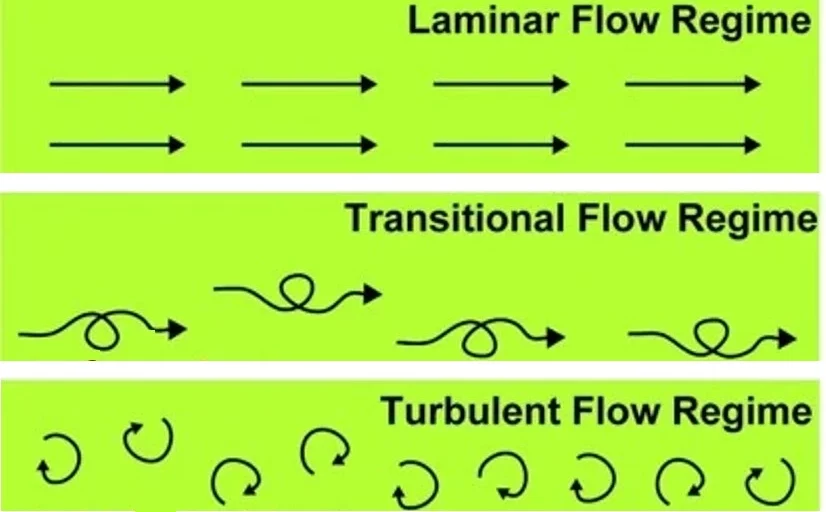
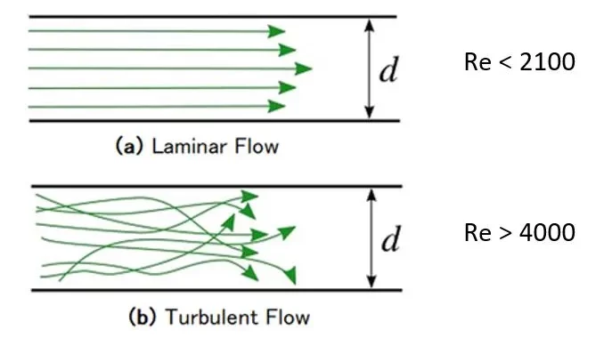
The flow is classified into laminar, transitional, or turbulent (Figure 2) depending on the fluid density and viscosity, characteristic velocity, geometry of the channel, and whether or not the flow is past the object [5].
For most simple microfluidic channels, the flow is laminar, with a width-to-height ratio of less than 1 mm and a characteristic velocity of less than a centimeter per second [5]. The molecular transport in the laminar flow differs from the turbulent as there is no convective mixing, but mixing occurs with the help of diffusion [6].
To better understand the miniaturized systems, it is necessary first to understand the physics behind microfluidics and how it affects fluid behavior. Flow behavior is typically a function of the Reynolds number, a measure of the ratio between inertial and viscous forces in a specific flow [6]. The dimensionless values are defined as [6]:
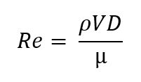
Where P is the fluid density, V is the mean fluid velocity, D is the pipe diameter, and µ is the dynamic viscosity.
This equation shows that the channel’s characteristic dimensions reduce, and the Reynolds number also falls. In circular tubes, flows with a Reynolds number less than 2100 typically indicate laminar flow, while flows with a Reynolds number greater than 4000 are turbulent (Figure 3) [6]. Between these values, the flow can switch between laminar and turbulent and is considered transitional [6].
In a microfluidic system with a rectangular channel, the transition between laminar and turbulent may occur with a Reynolds number between 200 and 700, possibly due to hydraulic diameter or aspect ratio [5].
Additionally, reaction times in microfluidic systems are much faster than in traditional systems [6]. This is explained by the smaller dimensions of the systems, which ultimately lead to a shorter diffusion time for any given molecule. The equation of the diffusion time is defined as [6]:
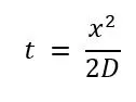
where x is the distance by one molecule of the solute along one axis after time t, and D is the solute’s diffusion coefficient.
Deadlines of European Programmes (Version 12/2025)
Get the MIC Horizon Europe 2026/2027 Calls Calendar:
-All Horizon Europe deadlines (by cluster and call).

Now that we better understand fluid dynamics at the microscale, we can have a look at the manufacturing technologies of microfluidic devices.
Manufacturing technologies in microfluidics
Conventional materials used in microfluidics
Until the end of the 20th century, elastomeric polydimethylsiloxane (PDMS) was the most used material for manufacturing microfluidic devices due to its unique characteristics (Figure 4) [6]. It is easy to mold, optically transparent, cheap, biocompatible, and suitable for prototyping. The fabrication method of PDMS material is simple and does not require a clean room.
Another advantage of this material is its simple bonding to other materials or itself [6]. PDMS’s elastomeric properties allow it to form a seal capable of withstanding moderate fluid pressures and create thin membranes that can be used to fabricate valves and pumps [6].
The device material can affect several things, such as flow, absorptivity, biocompatibility, and function of microfluidic components [9]. Common materials used in microfluidic device fabrication include polymers, PDMS, and inorganic materials such as glass and silicone, including those made with 3D printing [9].
Because conventional fabrication methods, like photolithography, wet/dry etching, and additive methods, evolved with MEMS technology, manufacturing first-generation microfluidic chips involved silicon. However, glass was soon adopted because of its stable electroosmotic flow, optical transparency, and resistance to organic solvents [9].
As many device fabrication technologies became available to the microfluidics community, the choice of materials became essential. Glass and silicon materials have the advantage of a well-defined fabrication protocol, and glass has superior properties such as chemical resistance and compatibility with optical detection methods [6]. However, both glass and silicon require complex and laborious fabrication steps. To this day, PDMS remains the most common material for microfluidic device fabrication due to its simple fabrication and relatively low cost [6].
Towards the turn of the century, there was an increased interest in polymer materials due to the need to develop existing micromanufacturing methods [6]. Polymethyl methacrylate (PMMA) was commonly used in microfluidics due to its rigidity, optical transparency, and suitability for high-throughput fabrication methods [6].
As with glass, researchers developed a PMMA device capable of performing electrophoresis and DNA sequencing [6]. Recently, many polymer materials, including polycarbonate (PC), polystyrene (PS), and cyclic olefin polymer (COC), have become frequently used in device fabrication, especially for embossed or injected molded parts [6].
21st-century microfluidics
With the development of new technologies, the start of the 21st century brought growth in the microfluidics research area, which led to the development of new microfluidics platforms for different research purposes [6]. Some of these technologies are briefly described in the following section.
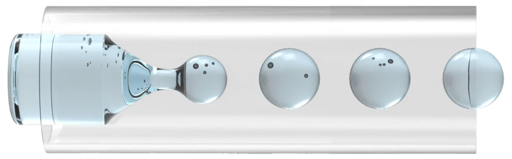
Droplet microfluidics
Droplet microfluidics (Figure 5) is a branch of microfluidics in which the reaction is encapsulated in a small compartment of emulsion [6]. The main advantage of a droplet is its high multiplex capabilities. Separate reactions can be encapsulated within a small volume of a few nanoliters, and thousands of reactions can occur simultaneously and independently. These capabilities have led to the development of this technique for high-throughput polymerase chain reaction (PCR), enzyme screening, and single-cell analysis [6].
Paper microfluidics
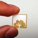
Because conventional microfluidic devices are expensive to produce, paper-based devices have been used as a substitute [6]. Using paper-based microfluidic systems (Figure 6) has several advantages. Paper serves as a good base for fluid movement, as the fluid is transported using capillary action. The technique has been widely used to produce commercial devices such as lateral flow assays, pregnancy tests, paper-based pH strips, and colorimetric glucose sensors [6].
Using paper instead of silicon and polymer substrates resulted in significantly reduced costs. It became realistic to fabricate microfluidic devices with a cost per unit of $0.10 [6]. In 2007, researchers in the Whitesides Group demonstrated how chromatographic papers could perform multiplex analysis of a solution, leading the paper analytical devices to the forefront of the microfluidics community [6].
This method involves printing a hydrophobic wax on filter paper and creating a well-defined channel to control the fluid flow [6]. After printing, the wax and the paper are heated in an oven to allow the wax to flow into the paper’s fibers, creating a hydrophobic barrier [6].
3D printing
Conventional fabrication methods, such as soft lithography, have been used for years to create microfluidic devices. Despite its invention in the late 1980s, 3D printing was maintained within the field of microfluidics until the late 2000s (Figure 4) [6]; it became one of the most powerful techniques that may overcome limitations in microfluidic research [9].
One of the important advantages of 3D printing is its low cost and reduced fabrication time compared to traditional methods like soft lithography and hot embossing [9]. Moreover, creating complex 3D structures and devices without a restrictive environment, such as a clean room, is possible.
The three main methods of 3D printing are fused deposition modeling (FDM), stereolithography (SLA), and polyjet (PJ) printing [9], with FDM being more commercially successful [6]. In this method, the thermoplastic is heated at a high temperature and extruded through a thin nozzle onto the stage in a predefined pattern [6]. After the deposition of one layer, the stage is moved down, and the next layer is deposited on top of the previous layer (Figure 7) [6].
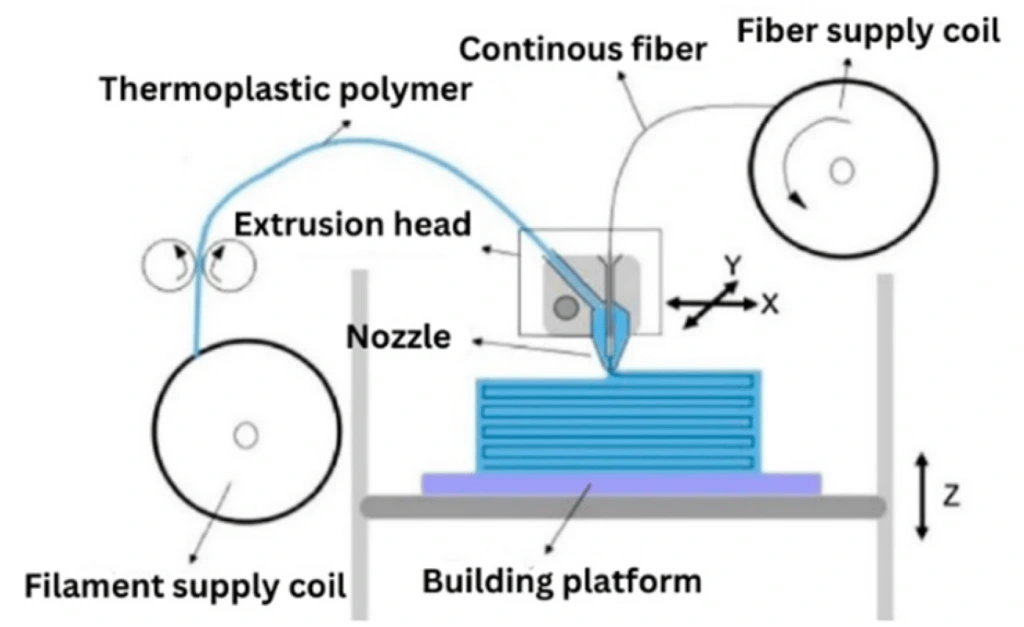
Each of FDM, SLA, and PJ requires creating a 3D computer-aided design of the desired microfluidic device, which is then converted to the stereolithography file, that the printer uses to print the device physically [9]. The FDM method is operated by extruding the solid filament through a heated nozzle in a liquid form onto the stage and applying the material layer by layer once the filament is solidified after each layer [9]. Although FDM is the cheapest and most user-friendly method, it has some drawbacks. The main limitations of this technique are the poor feature resolution and low optical transparency of the built materials [9].
The SLA method uses a laser or projected light image to polymerize layers in a liquid resin [9]. Once the first layer is hardened, the stage moves vertically so that liquid resin covers the solid layer, which allows the next layer to be polymerized [9]. This process is repeated until the device is complete. Lastly, PJ printing is operated by jetting a liquid photocurable resin, which solidifies after UV light exposure [9].
As described, each of the FDM, SLA, and PJ employs various building materials and has unique advantages and disadvantages [9].
Following this overview of microfluidics manufacturing techniques, it’s time to examine its main applications.
Applications of microfluidics
Nowadays, microfluidics has several applications in life science, such as lab-on-a-chip, organ-on-a-chip, point-of-care, cell analysis, drug delivery and administration, etc. We will focus here on lab-on-a-chip and organ-on-a-chip.
Lab-on-a-chip
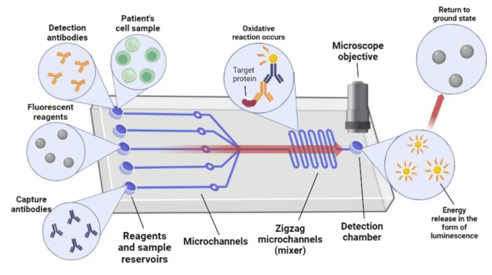
Lab-on-a-chip is a subset of micro-total-analysis systems derived from the hard and soft fabrication methods of miniaturized devices used for biochemical analysis (Figure 8). While the µTAS is referred to as a system composed of multiple chips, electronic units, and external sources, the lab-on-a-chip refers more specifically to a microfluidic chip or another device that performs a well-defined analytical task [5]. Lab-on-a-chip devices may include microsensors, microactuators, and customized surfaces made by chemical treatments or coatings with organic or inorganic materials [5].
Organ-on-a-chip
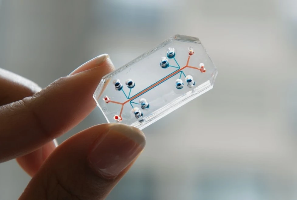
Organ-on-a-chip (OoC) is a biometric system created on a microfluidic chip and is recognized as one of the top ten emerging technologies in the World Economic Forum [6]. The environment in OoCs, similar to in vivo organs, recreates and dynamically controls their physiological processes [6].
Multiple OoCs representing different organs can be connected to form a body-on-a-chip technology [6]. The OoC technology can further be used as a model to predict human tissue response to various stimuli like drugs and environmental factors, contributing to the reduction and replacement of animal model use [6].
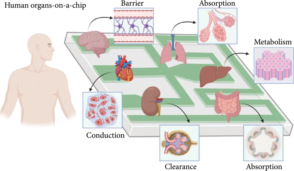
Organ-on-a-chip is a fast-growing and much-researched branch of microfluidics. This microfluidic cell culture system contains living cells arranged to simulate organ tissue [6]. OoC devices contain many features that define the majority of organs. One feature is the porous membrane that separates cells, and the constant flow also generates shear force analogous to the forces exerted on cells by the bloodstream, providing a more complete model of organ behavior [6]. Examples of OoC include lung, gut, liver, kidney, brain, heart, and many more (Figure 9).
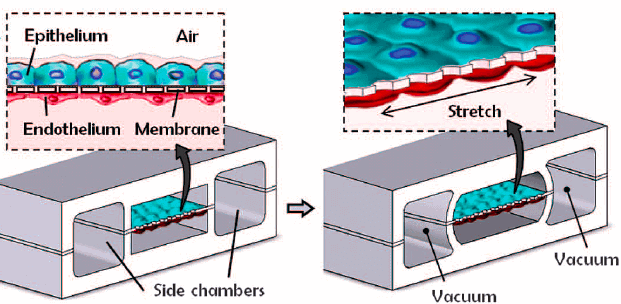
In 2010, Huh and colleagues created a biomimetic device designed to miniaturize the lung alveolar-capillary interface by replicating its structural, functional, and mechanical characteristics (Figure 10) [13]. This device consisted of two PDMS microchannels separated by a porous PDMS membrane, with human alveolar epithelial cells on one side and pulmonary endothelial cells on the other. By injecting air, they successfully simulated the human breathing process at the alveolar interface.
In 2016, Lee and colleagues introduced a one-step 3D bioprinting technique to develop organ-on-a-chip platforms, demonstrating the device’s capability of replicating the liver’s primary functions [14]. They utilized poly(e-caprolactone) as the platform’s base material, collagen and gelatin hydrogels encapsulating cells as inks to construct 3D platforms, and extracellular matrix-based hydrogels to mimic the microenvironment.
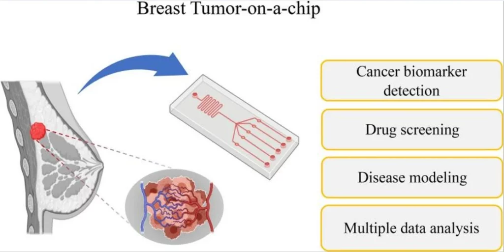
Cancer- or tumor-on-a-chip can be used for rapid disease diagnosis or modeling. In addition, it serves to investigate the mechanistic determinants of cancer metastasis, study a tumor’s response to drugs within a realistic microenvironment, or detect new biomarkers (Figure 11).
Future applications
We expect microfluidic technology to play a significant role in future point-of-care diagnosis and personalized therapy approaches using patients’ genetic and phenotypic data.
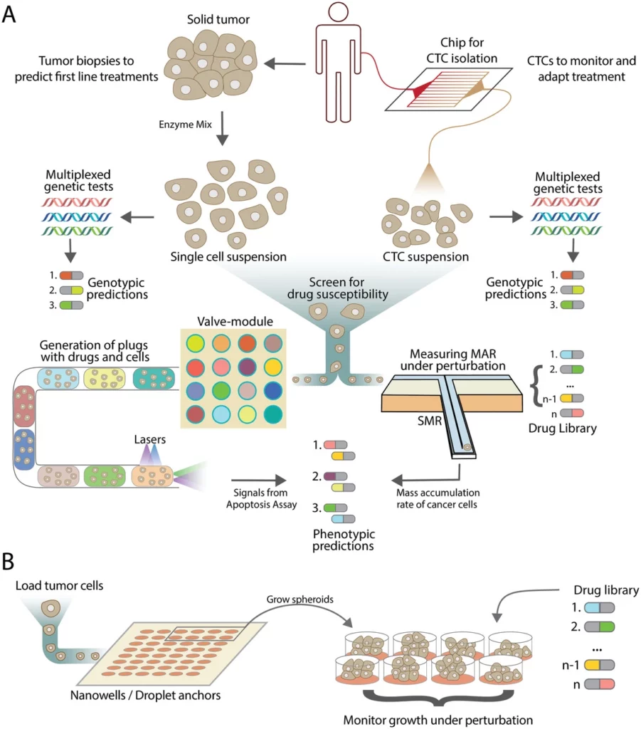
For example, here is a potential monitoring approach and functional and genetic cancer patient stratification based on microfluidics (Figure 12). Tumor biopsies can provide essential genetic and phenotypic information to guide the initial treatment strategy. Droplet-based microfluidic technology can isolate circulating tumor cells (CTCs) from patients, enabling disease state monitoring. The mass accumulation rate of these cells can be tracked using suspended microchannel resonators, which help determine drug susceptibilities of patient-derived tumor cells or CTCs. When combined with genotypic testing, this data allows clinicians to predict the efficacy of potential drugs based on patients’ genetic profiles [16].
Conclusion- The future of microfluidics
Microfluidics holds immense promise for the future, with its potential to revolutionize fields such as medicine, biology, and chemical engineering. However, the future of microfluidics is not without challenges. Scaling up the production of microfluidic devices while maintaining cost-effectiveness and ensuring consistent quality remains a significant hurdle. Additionally, integrating microfluidic systems with existing medical and laboratory infrastructure requires overcoming technical and regulatory barriers. Moreover, a considerable amount of data generated by microfluidic devices necessitates advanced analytical tools and expertise. Addressing these challenges is crucial for the transformative potential of microfluidics in various applications.
Funding and Support


This review was written by Diana Kafizova, R&D engineer, and Celeste Chidiac, PhD.
Published in August 2024.
Contact: Partnership[at]microfluidic.fr


References
- Folch, A., Introduction to BioMEMS. 1st ed. 2019: CRC Press.
- Choi, H. and C.C.M. Mody, The Long History of Molecular Electronics:Microelectronics Origins of Nanotechnology. Social Studies of Science, 2009. 39(1): p. 11-50.
- Heather, J.M. and B. Chain, The sequence of sequencers: The history of sequencing DNA. Genomics, 2016. 107(1): p. 1-8.
- Luni, C., E. Serena, and N. Elvassore, Human-on-chip for therapy development and fundamental science. Curr Opin Biotechnol, 2014. 25: p. 45-50.
- Saliterman, S., Fundamentals of BioMEMS and medical microdevices. Vol. 153. 2006: SPIE press.
- Convery, N. and N. Gadegaard, 30 years of microfluidics. Micro and Nano Engineering, 2019. 2: p. 76-91.
- Lesher, C.M., Up, down, or sideways: emplacement of magmatic Fe–Ni–Cu–PGE sulfide melts in large igneous provinces. Canadian Journal of Earth Sciences, 2019. 56(7): p. 756-773.
- geeks, G.f. Le numéro de Reynold. 2021; Available from: https://www.geeksforgeeks.org/reynolds-number/.
- Nielsen, J.B., et al., Microfluidics: innovations in materials and their fabrication and functionalization. Analytical chemistry, 2019. 92(1): p. 150-168.
- Iftekar, S., et al., Advancements and Limitations in 3D Printing Materials and Technologies: A Critical Review. Polymers 2023, 15, 2519. 2023.
- García-Hernández, L.A., et al., Optical detection of cancer cells using lab-on-a-chip. Biosensors, 2023. 13(4): p. 439.
- Li, J., et al., An Overview of Organs-on-Chips Based on Deep Learning. Research, 2022. 2022.
- Huh, D., et al., Reconstituting organ-level lung functions on a chip. Science, 2010. 328(5986): p. 1662-8.
- Lee, H. and D.-W. Cho, One-step fabrication of an organ-on-a-chip with spatial heterogeneity using a 3D bioprinting technology. Lab on a Chip, 2016. 16(14): p. 2618-2625.
- Subia, B., et al., Breast tumor-on-chip models: From disease modeling to personalized drug screening. Journal of Controlled Release, 2021. 331: p. 103-120.
- Mathur, L., et al., Microfluidics as an Enabling Technology for Personalized Cancer Therapy. Small, 2020. 16(9): p. 1904321.
Check the other Reviews
FAQ - The microfluidics revolution: manufacturing techniques and innovative applications
So just what is considered to be microfluidics, and why do fluids behave in such a different manner at that scale?
The field of microfluidics is concerned with fluids contained in extremely small volumes – usually systems in which at least one dimension measures less than 1 mm. When it becomes that small, microscopic forces, such as capillary effects, surface tension, viscous drag, etc., become important. The reason that you cannot just downscale a classical system is that the physics re-equilibrium scales do not always behave in an informally intuitive manner.
What is the history of microfluidics?
The historical path of the microfluidic-like devices is fairly logical: they began life as an extension of the electrophoresis systems (as early as the 1940s, basically, a thin sheet of fluid between the plates), and thereupon were heavily inspired by the microelectronics fabrication culture (the integrated-circuit age is an appropriate reference point). In the 1980s, genomics highlighted the need for high-sensitivity analysis with very small sample sizes. In the early 2000s, the disappointment with simplistic in vitro models accelerated the development of human-on-a-chip thinking. Read it like a chronology; it is not so much a revolution as a gradual movement of needs and means towards each other.
Why are scientists continuing to set up lab functions on chips–what are the benefits to the practical world?
It is difficult to resist a few repeat performances: significantly reduced reagent volumes, reaction times, and parallelization (many reactions at once, within a footprint which would otherwise hold a cup of coffee). Microchannel flow is also often laminar and hence more deterministic and mathematically manageable than most macroscopic flow problems. Well, you can make devices at the cellular scale to seed/sort/probe cells; it is plausible to automate them by adding valves, pumps, and routing logic to the chip. Added to this: portability, reduced unit cost in batch fabrication, and the potential for truly high-throughput workflows.
What are the building blocks of engineering of a microfluidic device?
Imagine a microfluidic system as a toolkit of functions: transport channels, controlled diffusion-based blending mixers, particle-handling filters, thermal control heat exchangers, and routing and metering valves and pumps. The review points out that hybrid devices – combining materials or components – are frequently important in practice since you might desire one material to be used in optics, another in flexibility (valves/membranes), and another in chemical resistance, which means that a chip is not a material slab that often behaves in a robust, instrument-like manner.
Where does PDMS still fall short, and when is it the right decision?
PDMS (polydimethylsiloxane) is not a bad choice of prototyping material: it can be easily molded, it is optically transparent, rather inexpensive, and sticks to itself (or other substrates) easily. Its elastomeric character is also a major factor, as it enables thin membranes, allowing on-chip valves and pumps without exotic fabrication. With that said, the review notes that material choice influences flow behavior, absorptivity, biocompatibility, and component functionality, so the fact that PDMS is common does not necessarily mean it is always the best choice when considering solvent compatibility, long-term stability, or scale-up.
Otherwise, what are the materials that prevail in more industrial or scalable processes other than PDMS?
The review provides the standard trade-off: silicon and glass are historically significant (clear protocols, optical transparency of glass, solvent resistance, constant electroosmotic flow), yet they are known to involve complex fabrication processes. Polymer families replaced this as the need arose to have more throughput methods of production- PMMA is specifically mentioned, as well as PC, PS, and COC, particularly when embossing or injection molding are involved. The lesson learned is that the optimum material is not about fashion but rather about what your end conditions demand: namely, optics, chemistry, throughput, bonding strategy, and regulatory environment.
What are the best of the new fabrication/application directions in the 21st century that we are talking about?
Three of them have been highlighted: droplet microfluidics, paper microfluidics, and 3D printing.
-Droplet microfluidics reactions can be compartmentalised in small emulsified droplets – typically nanoliters – enabling thousands of parallel, independent microreactors in things like high-throughput PCR, enzyme screening, and single-cell analysis.
-Paper microfluidics: intentionally low-cost, driven by capillary forces within porous paper; it is claimed that wax printing is a simple method for defining hydrophobic boundaries. The low-cost of some paper-based devices is appealing for resource-constrained diagnostics and mass-scale use.
-3D printing: it is no longer a hobby tool; it is being positioned as a means to overcome cleanroom limitations and create complex 3D geometries in very little time.
What are the actual alternatives- and the surprises? microfluidics in 3D-printed microfluidics.
The three primary methods are fused deposition modeling (FDM), stereolithography (SLA), and polyjet (PJ), as presented in the review. FDM is the most widely used and user-friendly, but it is also criticized for lower feature resolution and reduced optical transparency. SLA polymerizes resin layers with light, while PJ uses a photocurable resin and UV to cure. The printing process, material, and post-processing are silently determined to make it either a fast demo, a working prototype, or something you can actually rigorously test.
Lab-on-a-chip vs uTAS: Are these two terms that mean the same thing?
Not quite. The review strikes a more pragmatic difference: uTAS (micro total analysis systems) can be applied to a larger system: several chips and electronics, external sources, whereas lab-on-a-chip is a more focused term applied to a chip (or device) that characterizes a specific analyte. Lab-on-a-chip systems can include microsensors, microactuators, and custom surface chemistries (coatings, treatments) to enhance detection and specificity.
What is the big deal with organ-on-a-chip, as opposed to being another cell-culture device?
This is because it tries to mimic important physiological processes dynamically, not merely keep cells alive in a cool channel. Technically, it focuses on features such as porous membranes between cell layers, controlled shear forces under continuous flow, and the ability to connect several organ chips into body-on-a-chip designs. Two physical examples:
-A lung-on-a-chip, which has a copy of the alveolar-capillary interface between two PDMS microchannels separated by a porous PDMS membrane that is actuated by air to replicate breathing.
-One-step 3D bioprinting of a liver-like organ-on-a-chip platform based on poly (e-caprolactone) and cell-laden hydrogel ink.