A comparative guide of medium recirculation system setups
Author
Lisa Muiznieks, PhD, Celeste Chidiac, PhD, and Ilaria Ferraboschi, PhD candidate
Publication Date
Keywords
recirculation systems
Pressure pump & valve
Hydrostatic pressure
Infuse/withdraw syringe pump
Need advice for your recirculation system?
Your microfluidic SME partner for Horizon Europe
We take care of microfluidic engineering, work on valorization and optimize the proposal with you
What is “medium recirculation”? Why is it important, and how do you choose the best recirculation system? This page answers these questions and provides tips on selecting an adequate setup for your experiment.
Introduction to recirculation system
Fluid recirculation is an important function for organ-on-a-chip and microfluidic applications. It enables the transportation of nutrients, drugs, and cell secretions in a physiologically relevant circulating environment. Many recirculation systems have been developed over the years. When choosing a setup, the “most suitable” option often depends on the application, with features like volume and flow rate, tuneability, parallelization, and user-friendliness being important considerations.
This review briefly introduces the concept of fluid recirculation and describes more extensively some of the setups used nowadays in a microfluidic circuit. By describing the operating principles and highlighting the pros and cons of each method, we provide an essential and useful guide to users who want to approach these technologies for the first time.
Fluid recirculation system and microfluidics
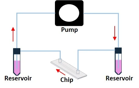
The fluid is highly controlled in a microfluidic circuit compared to conventional bench experiments (Figure 2) [1]. Thus, a wide range of lab-scale experiments can be replicated in a microfluidic device with higher precision, control, and less reagent usage.

Fluid recirculation system is a mechanism through which the fluids arriving at the chip outlet are reintroduced in the microfluidic circuit. It can be obtained in various ways depending on the experimental conditions, the pumps used, and the features we want to get from our flow (unidirectional or bidirectional, pulsatile, steady flow, and so on).
Fluid recirculation is an effective solution to various needs, such as:
- Long-lasting experiments (days, weeks)
- High flow rate
- Expensive reagents
- Non-adherent cell culture
- Medium enriching
- Better mimic of physiological conditions, like “multi-organ”
The next section will present some microfluidic recirculation system setups and describe their characteristics.
Recirculation system methods
Fluid movement is strictly connected to how the flow is generated. The pressure difference between a circuit’s beginning and end makes a liquid flow in a specific direction. The pressure difference can be generated through different forces, from a height difference between the inlet and outlet (hydrostatic pressure) to a generated pressure with pressure or vacuum pumps, which requires more technical skills but leads to a more controlled flow.
If we think about a flow driven by height difference, a switch in height difference will lead to fluid recirculation from the outlet to the inlet. In this case, the flow obtained is bidirectional, with little control over the flow rate. Syringe pumps can push or pull liquid at a programmable flow rate. A peristaltic pump forms a tight-closed loop by placing the outlet and the inlet in the same reservoir. When considering a flow generated by pressure/vacuum pumps, open loop setups are used to recirculate the liquid, and liquid flow can be unidirectional through the chip. Below, we discuss different recirculation systems that can be adapted to specific applications.
Hydrostatic pressure recirculation system
The hydrostatic pressure method consists of a flow generated by the height difference between the inlet and outlet and recirculated by switching the height difference (Figure 3).

One of the significant advantages of this method is its simplicity, as no electronic devices are required. Liquid can be topped up on either side of the chip by manual pipetting, thus enabling uni- or bi-directional flow. Large reservoir tanks can be connected to the chip inlet and outlet to maximize the flow duration. On the other hand, this simplicity is balanced by difficulty estimating flow rates through the chip and the low precision of flow rate control.
Many users employ a rocking principle for a flow controlled by the back-and-forth movement of a rocking platform (Figure 4). For most chip geometries, this recirculation system leads to a bidirectional flow. The user must consider whether this suits their cell type and application.

Chip manufacturers and researchers have designed different options for recirculation systems using this principle. For example, the OrganoFlow, developed by Mimetas company, is based on liquid passive leveling. The OrganoFlow allows interval rocking by switching sides every 5 sec, with adjustable rocking angles from 0° to 25°. The perfusion can be maintained indefinitely by placing the plates on the OrganoFlow.
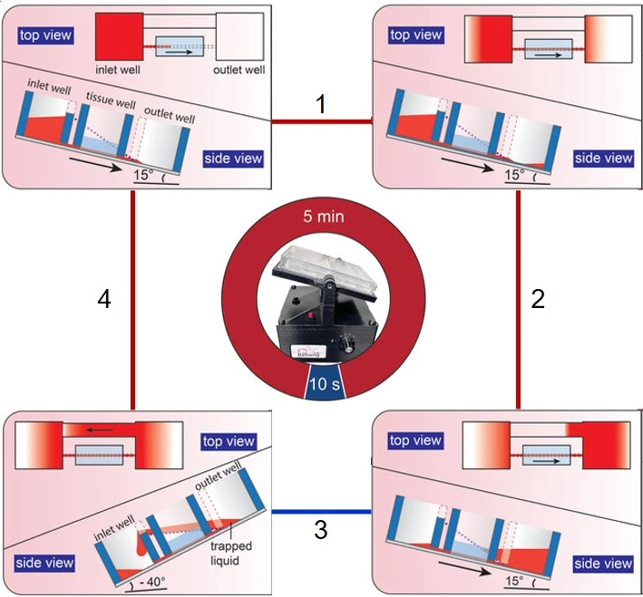
Zhang and colleagues have developed a pumpless rocking-based recirculating platform based on innovative chip geometry for a unidirectional flow. The designed plate contains three separate wells (inlet, tissue, and outlet wells) and a slanted bridge directly connected to the inlet and outlet wells. The rocker presents a tilt angle of 15° to allow the media to flow from the inlet to outlet wells through channels in the tissue well, then an angle of -40° to allow backflow from the outlet to the inlet wells through the slanted bridge without passing through the tissue well (Figure 5) [2].
Syringe pump recirculation system
Syringe pumps are a common instrument in life science labs and are widely used to generate a flow of media over cells in a downstream microfluidic chip (Figure 6, left). Syringe pumps can be used as a recirculation system. The user can set a specific flow rate, and the precision depends on the quality of the instrument. The liquid is typically pushed from the syringe until it is empty. Thus, users must consider the syringe volume when selecting the flow rate and length of time of the experiment to stay within the limits of the setup. Syringe pumps also typically produce flow oscillations due to motor steps. However, certain brands can minimize oscillation amplitude by using small-step stepper motors.
Programmable and bidirectional multi-syringe pumps can be used. These syringe pumps can be programmed to push and pull the fluid, creating a continuous push/withdraw flow cycle. In this case, when the syringe empties, the plunger reverses direction, drawing fluid back from the microfluidic device before pushing it in again (Figure 6, right).

Loop recirculation systems
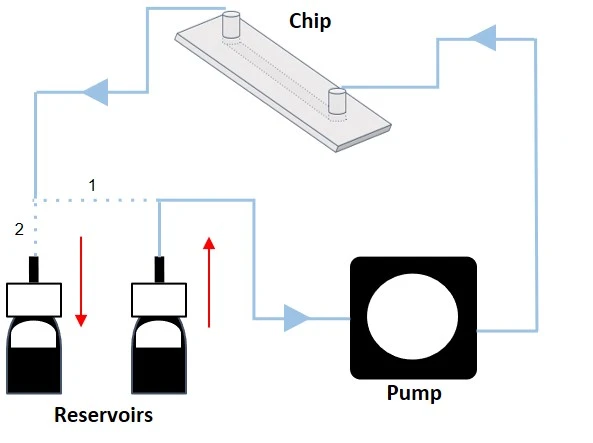
The loop is another method to obtain fluid recirculation in a tight-closed microfluidic circuit with peristaltic pumps or an open circuit with pressure pumps (Figure 7).
Peristaltic pump recirculation system
Unidirectional tight-closed loop
A peristaltic pump is a common instrument in life science labs. It provides one of the most straightforward options for moving liquid in a unidirectional loop (also called tight-closed; Figure 8). This method uses one reservoir from which equal volumes of liquid are simultaneously withdrawn and collected, maintaining a steady liquid level.

This method provides an efficient and user-friendly recirculation system, but a pulsatile flow is typically generated due to the rotor motion of the pump. Adding a pulsation dampener to the line can help reduce pulsation, e.g., a vessel of pressurized air in a discharge line or a trapped air pocket above a liquid reservoir. As fluid travels through the dampener, the trapped air can absorb as much as 90% of the pulsations to create a smoother fluid flow. In addition, making the length of the discharge tubing much longer or selecting a softer tubing material, such as silicone, can reduce pulsation by as much as 60%.
Peristaltic pumps also work by pinching the liquid as it passes through the rollers in the pump. Users must consider if this pinching motion will affect the integrity of any suspended particles or cells circulating in the liquid for their application.
Pressure pump recirculation systems
Bidirectional open loop
Pressure-driven flow control generates a pressure differential (ΔP) between the inlet and outlet of a circuit by pressurizing the air above the liquid in a reservoir. The flow rate is proportional to ΔP, i.e., the higher the pressure differential, the faster the flow. Combining a pressure-driven flow controller and a flow sensor with a feedback loop leads to a highly stable flow rate, suitable for both basic and advanced experiments (Figure 9). Think of it like keeping a constant speed when driving up a hill by adjusting how much the gas pedal is pressed.
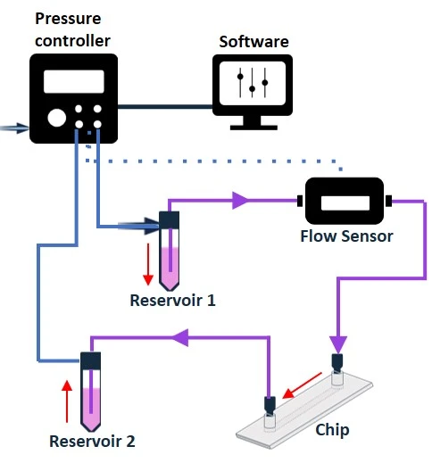
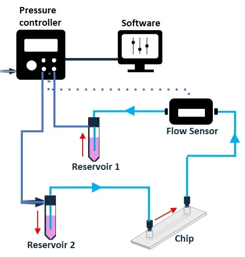
Figure 9: Bidirectional recirculation system setup from reservoir 1 to reservoir 2 (left), and from reservoir 2 to reservoir 1 (right).
In its simplest configuration, where a microfluidic chip is connected between 2 reservoirs and no additional valve system is used (Figure 9), this method results in a bidirectional recirculation system through the chip. However, adding a valve system to the circuit transforms the control of the flow path to enable unidirectional flow over cells.
The following section presents three valve systems for obtaining a unidirectional flow over cells with a pressure-driven flow controller.
Unidirectional open loop
Recirculation system with rotary valve
A rotary valve (e.g., MUX recirculation 6/2; Elveflow) allows fluid recirculation while maintaining a unidirectional and controlled flow. The MUX recirculation 6/2 is so named as it is a multiplexer valve with six bidirectional ports and two user-selectable positions (Figure 10).
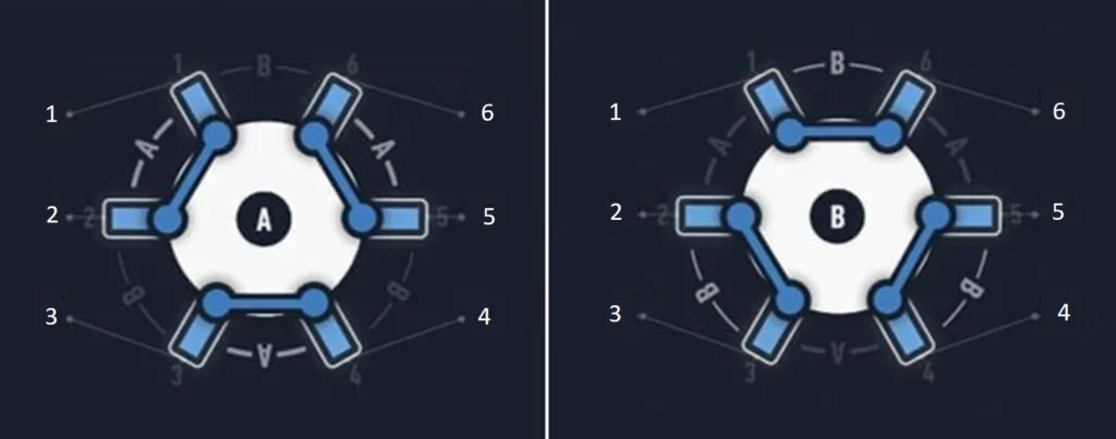
The two different valve positions allow the creation of 2 different flow paths through the full circuit (Figure 11). Connection of the modules to the six ports in a specific configuration will enable the alternate flow of medium into the valve from either reservoir 1 or reservoir 2, while maintaining one common exit port from the valve in both cases. Connecting the chip to this single exit port will enable unidirectional flow into the chip, regardless of which reservoir the liquid is coming from. The timing of valve position and reservoir pressurization switches can be automated using a software.
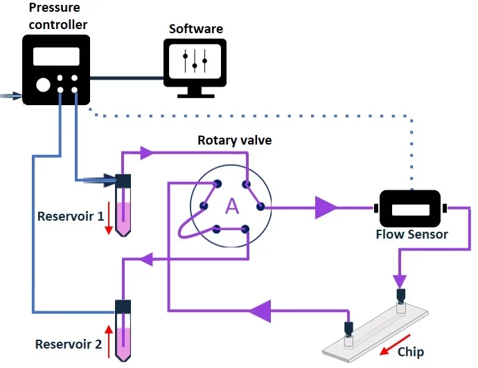
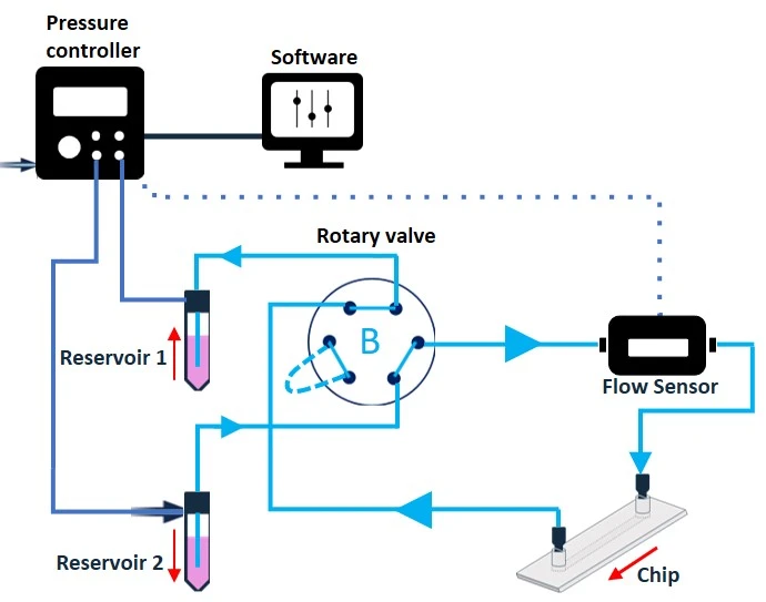
Figure 11: Recirculation system with a rotary valve from reservoir 1 to reservoir 2 (valve in position A), and from reservoir 2 to reservoir 1 (valve in position B). Note that the liquid exits the valve and flows towards the chip from the same port in both cases, enabling continuous unidirectional flow over cells.
Although the rotary recirculation valve provides very effective recirculation, it should not be placed inside a CO2 incubator and only supports recirculation in one microfluidic chip at a time.
Recirculation system with 3/2 valve
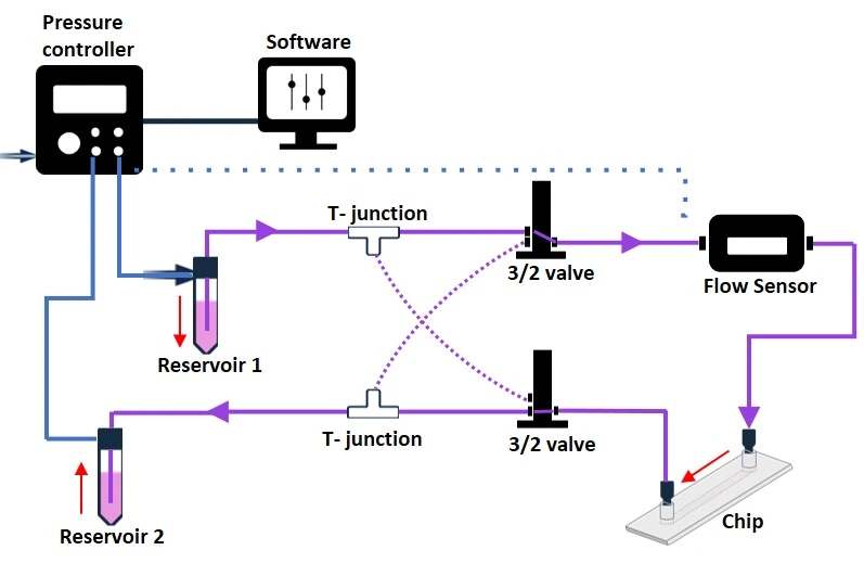
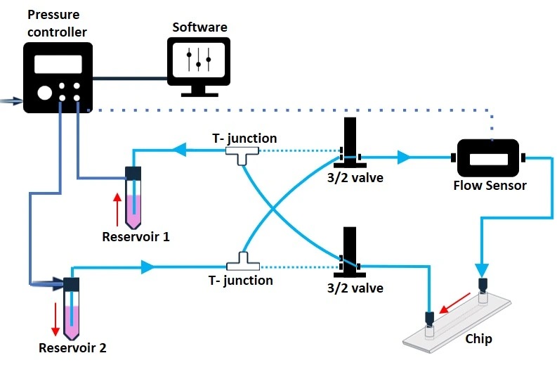
The 3/2 valve is a solenoid active valve with three bidirectional ports and two selectable positions that control the flow direction in a recirculation system. Connecting 2 x 3/2 valves and 2 T-junctions will enable unidirectional recirculation of the medium through a microfluidic chip (Figure 12). The 3/2 valve must be connected to a MUX wire (e.g., Elveflow) that can simultaneously control up to 16 different 3/2 valves.
The whole fluidic configuration can be controlled and automated by a software. Notably, the 3/2 valves are smaller than the rotary valve and may offer more flexibility, depending on the application needs. For example, extra 3/2 valves can be included to break the circuit, add reagents, or collect samples. However, like the rotary valve, 3/2 valves are electronic modules that should not be used in the CO2 incubator.
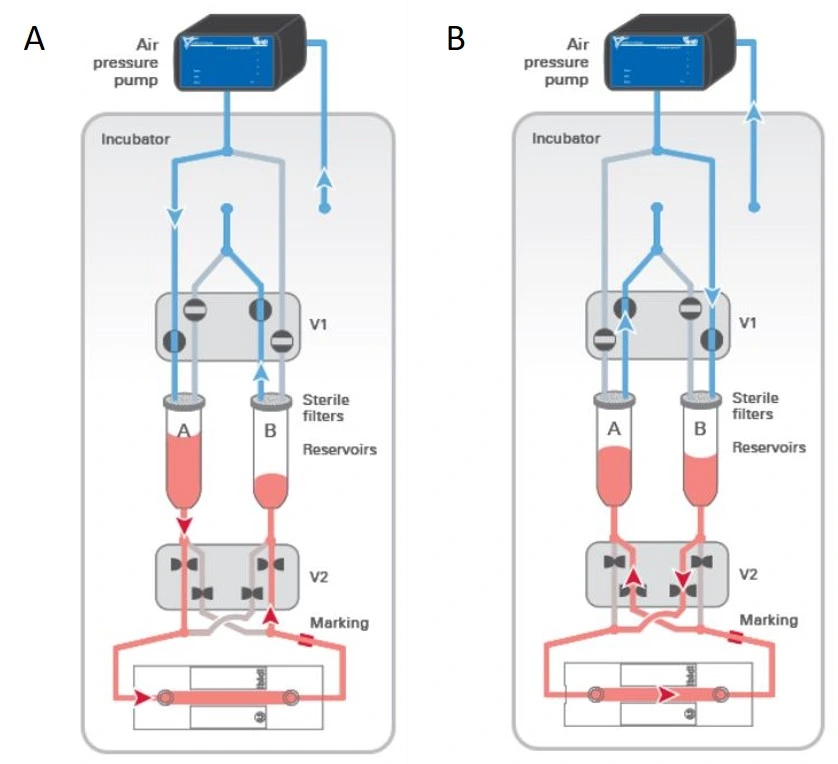
A similar pump system designed by ibidi employs a pinch valve instead of a 3/2 valve. The two devices share the same working principle, but while the 3/2 valve switches to a different flow path to block the fluid, the pinch valve squeezes the tubing to stop the liquid from flowing (Figure 13). Although the pinch valve has a defined lifetime, one of its most significant advantages is that it can be placed inside the incubator, so the entire flow path can more easily be kept at 37°C during an experiment.
Recirculation system with check valves
A passive valve system (e.g., self-acting valves) is an alternative to active valves (e.g., those requiring an external input to change the configuration, like an electrical command).
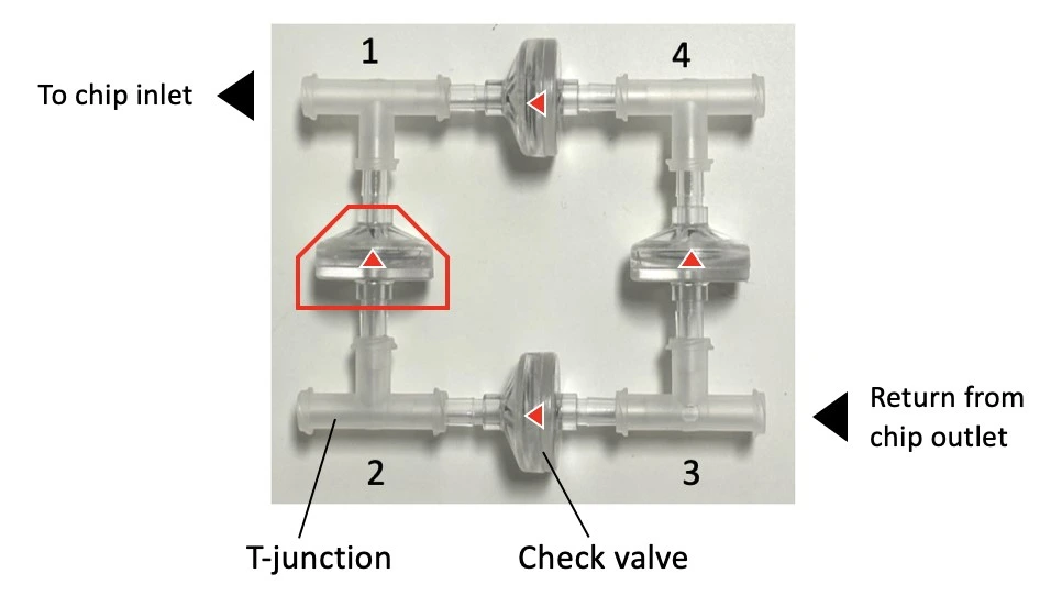
The MIC automated recirculation system is based on a passive check valve setup and is suitable for recirculation using a pressure-driven flow controller (Figure 14).


The 4-check valve system is designed as a square “recirculation bridge”, with one check valve on each side and one T-junction at each corner to split the incoming flow (MIC, Figure 15). A check valve is a conical device that allows flow in one direction (an arrow on the side indicates the flow direction: outwards from the triangular apex) and blocks backflow with a flexible internal membrane.
The orientation of each valve is crucial for correct system functioning: each pair of parallel valves should be oriented in the same direction. The corner whose nearest two valves flow towards it (corner 1, Figure 15) is the common exit from the bridge and should be connected to the chip. The opposite corner (corner 3, Figure 15) has its nearest two valves presenting their flat face towards it and is the point of entry from the chip back into the bridge. The two remaining corners of the bridge should be connected to the two liquid reservoirs. In this configuration, the flow will always be unidirectional through the chip, regardless of which reservoir the liquid is pushed from.
The check valve system can be autoclaved and used inside a CO2 incubator.
Check this video and this application note that explain how to assemble the recirculation bridge and set up your system.
For extra advantages, a pair of level sensors (MIC, Figure 16) can be added for a continuous and automated recirculation system (Figure 17) based on real-time sensor data, eliminating the need for time calculation and manual intervention by the operator. They are capacitive sensors that measure the level of the medium in the reservoirs and automatically stop pressurizing a reservoir when a minimal volume remains.
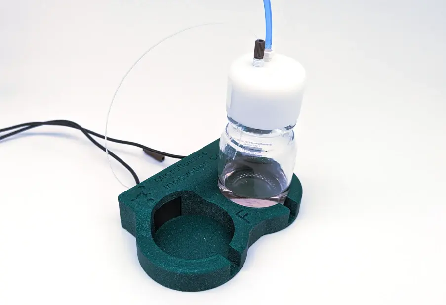
Level sensors effectively introduce a fail-safe mechanism against asymmetrical volumes of liquid passing between reservoirs in successive pressurization switches. This protects against air introduction over the cells due to the ever-evolving nature of a recirculation system, such as leakage, clogging, or fouling of the tubing with cell debris or secretions leading to flow sensor drift. This feature is especially useful for long-term experiments (multi-day to weeks) or if the application uses fast flow rates that require many switches.
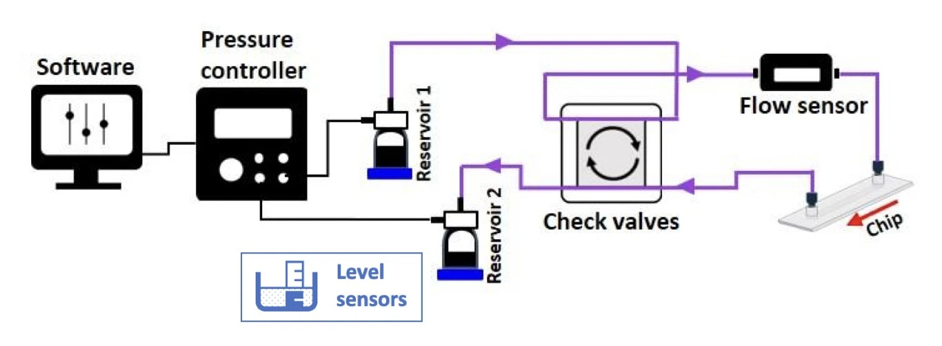
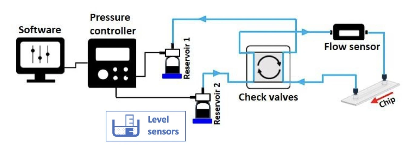
Our team tested the check valves’ ability to perform 60 hours of continuous cell perfusion. The reservoirs, check valves, and flow sensor were placed inside a CO2 incubator. The flow rate was set at 20 µl/min, and the pressurization switches between alternate reservoirs were scheduled through the software every 5 hours (Figure 18).

Moreover, the cell culture pump (MIC, Figure 19) can be used in the setup as a pressure controller for a recirculation system outside of a CO2 incubator. In this case, an additional stage-top incubator should be used to keep the temperature stable for long periods, allowing for high-quality live cell imaging experiments or more portable and convenient bench-top handling.
The cell culture pump consumes less gas than other pressure-driven flow controllers. Pressuring the media reservoir with the correct gas mix prevents the gas in the media from diffusing into the atmospheric air. The constant media flow ensures that the correct composition always reaches the cells, even if the rest of the system is not gas-tight.
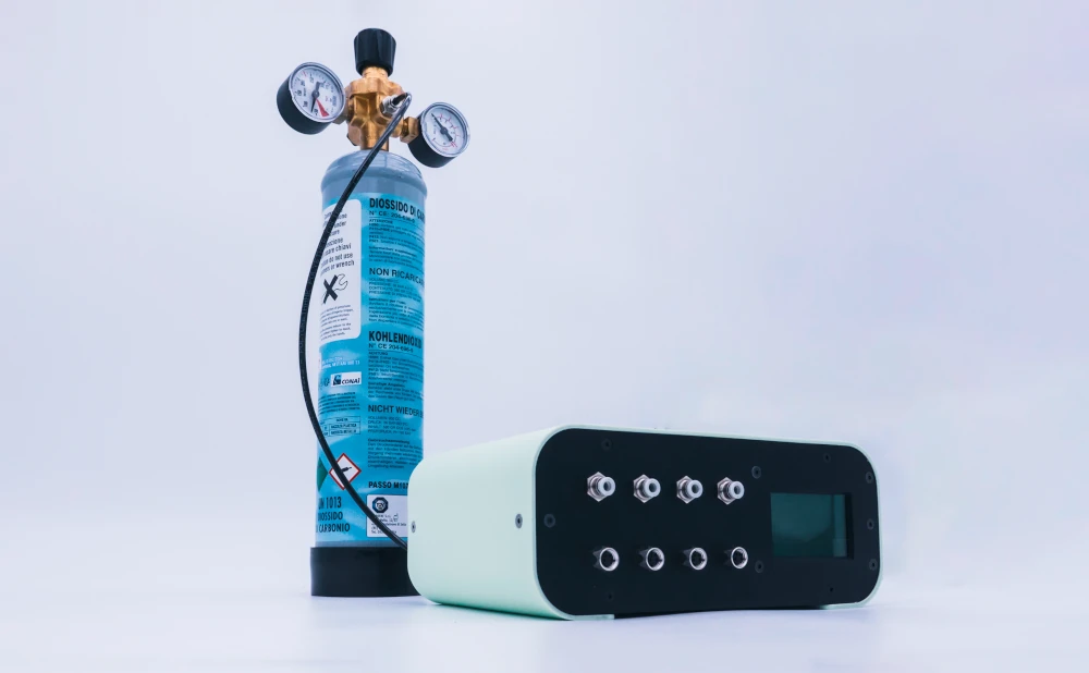
Figure 19: Cell culture pump, MIC.
Check this page comparing our unidirectional automated recirculation system to recirculation with a peristaltic pump.
Conclusion
This guide has examined various methodologies for implementing microfluidic fluid recirculation systems, encompassing fundamental and advanced experimental approaches. The table below summarizes the main characteristics of each system. Ultimately, selecting an appropriate technique will depend on the specific requirements of the biological application, the user’s expertise, and the resources available to them. This nuanced understanding will enable researchers to tailor their experimental designs to optimize performance and outcomes in their respective fields.
Characteristics/ Recirculation systems | Flow directionality | Flow rate control | Flow profile | CO2 incubator |
Hydrostatic pressure | Normally bidirectional with a rocker; Can be unidirectional with manual liquid replacement | None to limited; Can be controlled using a programmable rocking platform | Affected by rocker speed and tilt angle, and/ or reservoir height and liquid volume | Might need a CO2 incubator, some rockers can go inside the incubator |
Infuse/withdraw syringe pump | Normally bidirectional | Controlled by the pump | Amplitude of screw-motion; pulsatility depends on pump | Might need a CO2 incubator |
Peristaltic pump | Unidirectional flow | Controlled by the pump | Moderately pulsatile flow; Can be reduced with a dampener | Might need a CO2 incubator |
Pressure pump and valve | Unidirectional flow with the use of rotary valve, 3/2 valve, or check valves | Precise flow rate control; Uses flow sensor feedback loop | Highly stable profile; Variety of flows possible: pulsatile, steady, stepwise, custom | No need for a CO2 incubator with the cell culture pump; Might need a stage-top incubator |
Funding and Support
This review was written under funding from the European Union programs
H2020-MSCA-RISE-2020, grant agreement no. 101007804 (Micro4Nano, project page),
H2020-LC-GD-2020-3, grant agreement no. 101036702 (LIFESAVER, project page),
and H2020-LC-GD-2020-3, grant agreement no. 101037090 (ALTERNATIVE, project page).



This “quick tips” was written by Lisa Muiznieks, PhD, Celeste Chidiac, PhD, and Ilaria Ferraboschi, PhD candidate.
Published in October 2024.
Contact: Partnership[at]microfluidic.fr



References
- Lesher, M., Up, Down, or Sideways: Emplacement of Magmatic Ni-Cu-(PGE) Sulfide Melts in Large Igneous Provinces. Canadian Journal of Earth Sciences, 2019. 56.
- Zhang, F., et al., Pump-Less Platform Enables Long-Term Recirculating Perfusion of 3D Printed Tubular Tissues. Advanced Healthcare Materials, 2023. 12(27): p. 2300423
Check more Quick Tips
FAQ - A comparative guide of medium recirculation system setups
What is the medium recirculation, and why is it significant in microfluidics?
Medium recirculation is a mechanism through which fluids exiting a microfluidic chip are reintroduced into the circuit rather than discarded. This allows the circulation of nutrients, drug delivery, and cell secretion in physiologically significant environments. Long-term experiments, applications that demand high flow rates or costly reagents, non-adherent cell cultures, medium enrichment experiments, and closer recapitulation of physiological conditions, such as multi-organ systems with organs connected by shared circulation, are all applications of recirculation.
What are the key benefits of hydrostatic pressure recirculation systems?
Hydrostatic pressure systems are very simple because they require no electronic components; flow is generated solely by the difference in height between the inlet and outlet reservoirs. Liquid can be pipetted manually by the user for unidirectional or bidirectional flow, and large reservoir tanks provide the maximum flow time. This simplicity, however, comes with trade-offs: flow rate estimation is challenging, flow rate control is not highly precise, and flow rate patterns are usually bidirectional, which may not apply to all cell types and applications.
What about the rocking platforms with recirculation?
Rocking platforms alter the relative heights of the inlet and outlet reservoirs by tilting horizontally. Commercial systems such as OrganoFlow can be interval rocked by alternating sides every 5 seconds at angles of 0-25 degrees. Innovative designs achieve unidirectional flow by developing a new chip geometry with three discrete wells and a slanted bridge, in which media pass through tissue channels in one direction and through the bridge in the other, without traversing the tissue at any given time.
What are the most important peculiarities of syringe pump recirculation systems?
Syringe pumps provide tight flow rate control at user-selected settings, and the quality of the instruments determines accuracy. Normal working pushes the liquid until the syringe is empty, and users need to keep the syringe volume in mind when choosing flow rates and the duration of the experiment. Multi-syringe pumps with programmable bidirectional operations can be used to generate continuous push withdraw cycles, in which the direction of the plunger is reversed on an empty cycle to draw fluid back and then resume pushing. Nonetheless, motor steps normally oscillate the flow, even with small-step stepper motors, due to syringe pumps.
What is the distinction between the tight-closed loop and the open loop recirculation?
In tight-closed loop systems, which are generally operated with peristaltic pumps, the outlet tubing is connected directly to the inlet tubing via a single reservoir, where equal volumes are drawn and collected simultaneously, keeping the liquid level constant. Open-loop systems are used with pressure pumps and employ two separate reservoirs and two valves to regulate the direction of flow between them. The tight-closed configuration is simpler but tends to produce pulsatile flow, whereas open loops, with properly functioning valves, allow unidirectional flow and are more stable.
What are the principles used by peristaltic pumps to develop recirculation, and what are their shortcomings?
Peristaltic pumps are simple and offer unidirectional flow, as an equal volume of liquid is simultaneously withdrawn and collected within a single reservoir. But the rotor movement usually creates pulsatile flow, which can be minimized by adding pulsation-absorbing vessels (pressurized air that absorbs up to 90% of pulsations), longer discharge tubing, or by using less rigid materials such as silicone tubing. Also, pinching of the tubing can compromise the integrity of suspended particles or cells, and special precautions should be taken.
Why are pressure pump systems, which are valve-controlled, beneficial?
Flow controllers using pressure differences maintain constant pressure differentials between the inlet and outlet by pressurizing air over reservoir liquids. When these systems are coupled with flow sensors that provide feedback, extremely steady flow rates are achieved, suitable for both simple and sophisticated experiments. The incorporation of valve arrangements changes two-way arrangements into one-way flow layouts. These may be rotary valves, 3/2 solenoid valves, or passive check valves; each with its own benefits in the form of automation, incubator compatibility, and system complexity.
What are the working mechanisms of the check valve recirculation systems?
A Check valve system employs four conical apparatus installed in a square recirculation bridge arrangement, with each apparatus capable of allowing flow in a single direction and preventing backflow using flexible internal membranes. The correct orientation provides a chip entry point and a chip exit point, where the nearest valves approach with their flat faces. This flow is unidirectional through the chip, regardless of which reservoir is pressurized. These may be autoclaved, placed within CO2 incubators, and supplemented with level sensors to run automatically in the long term.
How can level sensors be used in automated recirculation?
Capacitive level sensors measure the volume of the medium in reservoirs and automatically deactivate pressurization when little volume remains, enabling continuous automated recirculation based on real-time data rather than time-based calculations. They contain fail-safe mechanisms to prevent asymmetric volume transfer between successive pressurization switches and to guard against the introduction of air into cells due to leakage, clogging, fouling, or flow sensor drift. This is particularly important in experiments or applications that require high-frequency reservoir switches, such as multi-day to multi-week experiments or high-flow-rate applications.
What are the comparisons of various recirculation systems to be used in CO2 incubators?
Hydrostatic pressure rockers and peristaltic pumps can typically be placed inside incubators, though some require external positioning. Syringe pumps may require incubators, depending on the design. Electronic valve systems, including rotary valves and 3/2 valves, generally cannot operate inside incubators, requiring stage-top incubators for temperature control. Passive check valve systems excel in incubator compatibility as they can be fully autoclaved and positioned inside, along with reservoirs and flow sensors. Cell culture pumps designed for minimal gas consumption can be used outside incubators when paired with stage-top incubators for convenient bench-top handling.

