Circular channel fabrication in microfluidic devices
Author
Oore-ofe Akeredolu
Publication Date
September 28, 2020
Keywords
circular channel
Microfluidic cell-culture
soft lithography
hot-embossing
Need advice for your circular channel fabrication?
Your microfluidic SME partner for Horizon Europe
We take care of microfluidic engineering, work on valorization and optimize the proposal with you
Circular channels in microfluidic devices are complex structures, and their fabrication requires specific techniques not commonly implemented in mass production. Therefore, it is nearly impossible to find microfluidic devices with circular channels today.

In this review, we will present the fabrication of circular microfluidic channels using a metal wire and the example of an artery-on-a-chip model.
Introduction to circular channels and their applications in microfluidics
Only a few representative models of vasculature and, specifically, carotid arteries have been developed so far, and existing models are not fully adapted to study the effects of disease, like the consequences of a stroke, on vascular cells. The most advanced models require laboratory animals or human trials, which raises ethical concerns.
The main objective of this study was to develop a novel microfluidic model with circular channels on the chip that combines strategically designed polymeric structures for cell culture to mimic the human vascular system in a reproducible way.
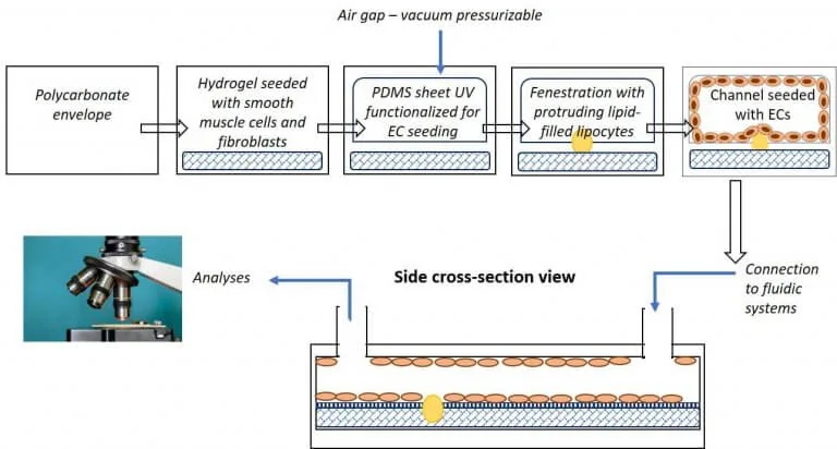
A microfluidic platform provides the added advantage of a controlled flow within the designed chip and its channels to assess the effects on cells. Figure 2 shows a schematic representation of a microfluidic artery-on-a-chip model and the use of circular channels within the device.
Microfabrication of circular channels
Using soft lithography
Standard microfluidic chips on the market have a rectangular cross-section of their channels due to technical limitations during manufacture.
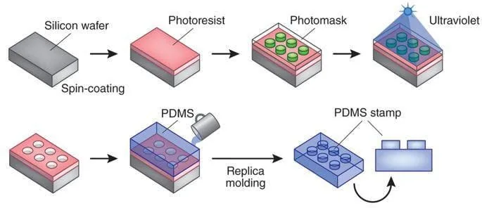
Standard PDMS procedures use photolithography to fabricate a mold using a damaging photoresist liquid or dry film resist such as Ordyl©. The mold is laser etched from a predesigned mask into the desired pattern for the microfluidic chamber. The developed mold is then used as a frame for the liquid silicone elastomer base, PDMS, which solidifies to form the desired chamber design (Figure 2).
Multiple chambers with the same design can be fabricated by simply reusing the mask to produce the desired molds and pouring the PDMS to form an equivalent number of chambers. Here, we tried to create PDMS microfluidic chips with a circular cross-section of the channels. Such chips are currently not commercially available but would mimic the human blood vessel more accurately than devices with rectangular channels.
A channel structure with a circular cross-section would ensure biophysically representative fluid flow properties and shear forces inside the device. Unfortunately, the first attempts to produce microfluidic chips with circular channels showed that PDMS was unsuitable for this channel architecture as the manufacturing method is limited and reserved for channels with rectangular structures.
Using hot-embossing
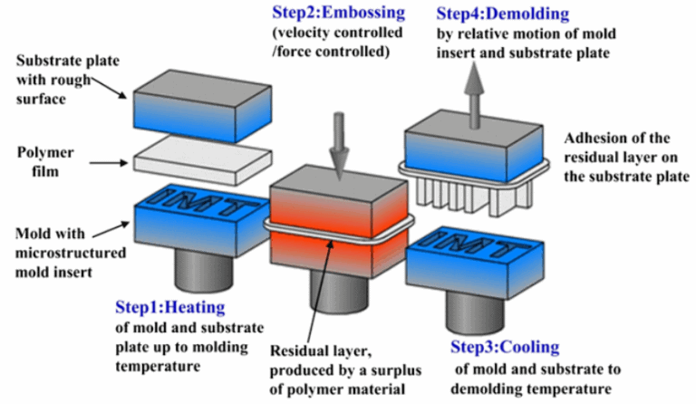
Since PDMS was unsuitable for fabricating circular channels, we tried alternative approaches and settled for hot embossing using Flexdym®. An overview of the process of hot embossing is shown in Figure 3.
The styrene ethylene-butylene block copolymer thermoplastic Flexdym® that Eden Microfluidics has developed has already been successfully used for cell culture. We fabricated circular channels using a metal wire of the desired diameter, which was inserted between two layers of Flexdym® before hot-embossing and extracted after the mold had cooled down.
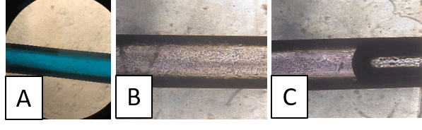
Using this technique, we could fabricate circular channels reproducibly using a metal wire with the initially proposed lumen diameter of 6.0 mm. The results are shown in Figure 4.
Microfluidic cell-culture in a circular channel
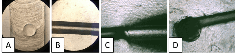
The microfluidic chip fabricated in Flexdym® was first assessed visually using dyed water to demonstrate uninterrupted laminar flow before seeding cells within the channel (Figure 5A and D). Following validation, HEK 293 cells were manually seeded into the device at 100 x 105 cells/mL concentration by pipetting. After 2 and 3 hours of incubation, the seeded cells were confirmed to have successfully attached to the walls of the device (Figures 5B and C).
DMEM growth media supplemented with CS (10%) Penicillin/Streptomycin was passed in through the chip twice every 4 hours by manual pipetting to sustain the cells for up to 3 days. These results were demonstrated to be reproducible with three similar fabricated chips.
Conclusions and perspectives
A microfluidic chip with circular channels is a prerequisite for an artery-on-a-chip model close to natural human physiology. This first attempt to manufacture circular channels in a microfluidic chip showed that it is possible to have a defined channel with the desired diameter.
Further, it was demonstrated that cells adhere successfully to the channel walls and that perfusion of the microfluidic chip is successfully maintaining the cells in culture. As a further step, the chip could be connected to an automated microfluidic perfusion system to reduce manual manipulations. In addition, introducing branches to the channel would be a challenging further development.
Review done thanks to the support of the H2020-MSCA-IF Action CAR-OAC, Grant agreement number: 843279
Author: Oore-ofe Akeredolu, Research engineer
Contact:
Partnership[at]microfluidic.fr

Check the other Reviews
FAQ - Circular channel fabrication in microfluidic devices
Why do we need circular channels of microfluidic devices?
Circular channels play a vital role in developing more robust biological models, especially in vascular research. Circular cross-sections are preferred over regular rectangular ones because they are more similar to the natural physiology of human blood vessels. The geometry provides biophysically relevant fluid flow and shear forces, which are needed to develop an understanding of how diseases, including strokes, can affect vascular cells in an arterial-on-a-chip system.
Why are the channels of most commercial microfluidic chips rectangular?
The number of rectangular channels is largely due to technical constraints in the standard manufacturing process. Soft lithography is used to make most microfluidic devices, which involve creating a mold by photolithography. Features created through this process typically have vertical sidewalls and are rectangular. Although it is good for mass production, it does not produce rounded geometries effectively in circular channels.
What makes PDMS inappropriate for the production of circular channels?
Microfluidics is typically fabricated using polydimethylsiloxane (PDMS) via soft lithography. Efforts to use PDMS in circular channels have proved unsuccessful due to the nature of mould-making methods, which are designed only for rectangular moulds. This means that PDMS is not the best candidate for building the rounded, tubular structures required to model real vessels.
What other material was ever able to produce circular channels?
The review mentions the application of Flexdym(r), a thermoplastic made from a styrene-ethylene-butylene block copolymer produced by Eden Microfluidics. In contrast to PDMS, Flexdym(r) can be used in the hot-embossing process and has been demonstrated to be compatible with cell culture, so Flexdym(r) can also be used to fabricate devices with circular geometries.
How are these circular channels made? What is the technique of the fabrication?
The effective process mentioned is the hot-embossing. A metal wire with the desired diameter (e.g, 6.0 mm) is placed between two layers of Flexdym(r). The product is then exposed to heat and pressure (usually approximately 150 °C). After the mold is left to cool, the wire is removed, leaving a continuous reproducible circular channel in the device.
Do these circular channels allow successful culturing of cells?
Yes. The experiment established that the HEK 293 cells were manually seeded in the Flexdym(r) circular channels. Incubation of the cells took 2 to 3 hours after which the cells attached successfully to the curved channel walls. Up to 3 days of maintenance on the device by hand perfusion of growth media demonstrated that the device was viable in short-term cell culture.
What was the quality of flow in the circular channels?
Prior to cell introduction, a visual assessment of the devices was done using dyed water. The tests verified the existence of a continuous laminar flow profile in the channel. This laminar flow is essential to microfluidic applications because it enables the reliable future behavior of fluids, which is needed to control experiments and provide a stable cell culture environment.
Which model is referred to as the artery-on-a-chip?
The artery-on-a-chip model is an example of a microfluidic platform designed to represent the human vascular system. The model provides a more physiological environment for culturing vascular cells by using circular rather than rectangular channels. This enables scientists to research vascular diseases and drug reactions in a system with much resemblance to a human body that may eliminate the use of animals in testing.
What are the significant issues or constraints of the existing prototype of the circular channel? Although the existing process manages to produce easy circular channels, the fabrication process remains mostly manual. In the study, cell seeding and media perfusion were done manually through pipetting. Also, the present design is based on a single straight channel, and one of the future directions the design may take is to incorporate complex geometries, i.e. the introduction of branches or a bifurcation (to replicate a physical vascular network).
What do the future hold of this technology?
The further evolution of the device will be geared towards making it more usable and complex. Major objectives also include interfacing the chip with an automated liquid-perfusion in a microfluidic device to eliminate manual liquid manipulation. In addition, scientists will modify the production method to enable branched channels, which would be useful for modeling more complex vascular networks.