Microfluidic Sensor Calibration Pack
Test, characterize and calibrate a microfluidic sensor with this pack
Easy concentration calibration
Calibrate sensors using different concentrations by mixing two fluids
Multiple sample injection
An integrated MUX distributor for injecting different samples sensors
Automated calibration
Straightforward sequence personalization

Need a microfluidic SME partner for your Horizon Europe project?
Microfluidic sensor calibration
This sensor calibration pack is dedicated to testing, characterizing, and calibrating sensors with small volumes and remarkable precision. This pack is highly adaptable and can include different features. For example, the ability to inject different sample concentrations using a mixing step and perform a sequential fluid injection can be included.
This pack is ideally suited for applications such as calibrating a colorimetric sensor to determine a particular chemical concentration by automatically injecting samples with different concentrations sequentially. It could also be used for pH sensors, biosensors, electrochemical sensors …
This pack can be adapted for a wide variety of liquids and gases.
Based on a high-accuracy flow controller, this all-in-one solution contains all the required parts for researchers to set up their microfluidic sensor calibration. Our experts will support the setup and start of the microfluidic experiment, making this pack usable for beginners in microfluidic technology.
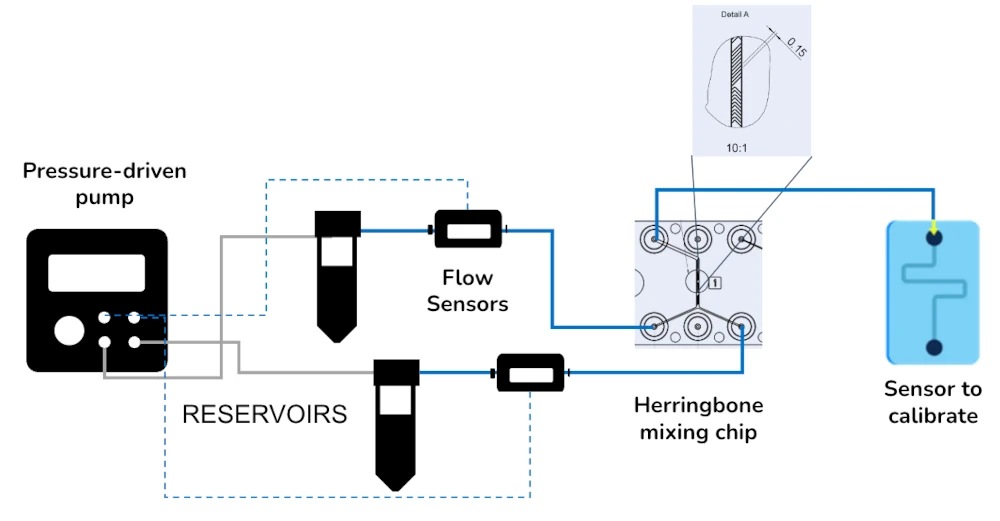
A sensor calibration of all included packs for microfluidic sensors can be adapted to your specific application. A herringbone chip can be included to perform a mixing between two fluids before the injection of the resulting sample into the sensors. Swapping quickly between different samples is also possible thanks to a rotary valve.
One of the critical parameters to consider when calibrating a sensor in the microfluidic chip is the flow rate control’s precision and stability. The flow controller can be coupled with a microfluidic flow sensor (eg. Galileo).
Sensor calibration pack setup
An all-in-one pack guarantees good compatibility between the different instruments, allows you to start your experiment immediately, is piloted by a single software, and can be used for other applications. These are a few reasons why an all-in-one pack is the easiest way to set up your microfluidic experiment. Our experts will bring support and expertise during the department’s sign and implementation.
Two examples of sensor calibration packs are introduced below, enabling the calibration of a sensor in a microfluidic chip with different concentrations via a mixing step with the injection of several samples. Our multiple fluid switching application pack contains more detailed information about sequential fluid injection.
Sensor calibration example pack 1 (concentration calibration):

Flow sensor (Galileo, MIC)
Software (Galileo user interface)
Pressure controller
Reservoirs
Microfluidic chip 187 from microfluidic ChipShop
The sensor to test or calibrate
Sensor calibration example pack 2 (sequential injection calibration):

Flow sensor (Galileo, MIC)
Software (Galileo user interface)
Pressure controller
Reservoirs
Sequential injection/distribution valve
Pressure splitter manifold
The sensor to test or calibrate
Sensor calibration principle
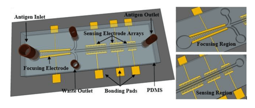
Sensors are a crucial component for the vast majority of microfluidic platforms developed for multiple applications. Microsensors can be used for cell counting, dielectric properties analysis, or size assessment [1-3], but they can also measure the concentration of electrolytes in horse urine samples [4] or detect phosphate [5].
Microfluidic platforms and sensors can have various applications, from biology to chemistry or medicine. Sensors can use different technologies and strategies to measure the relevant value for a specific application, such as optical sensors [6], mechanical sensors [7], and magnetic sensors [8], among others [9].
They can be directly integrated into a microfluidic chip [1-2] or outside of it, like the Elveflow pressure and flow sensors. Sensors must be calibrated before use to perform reproducible and precise measurements [10]. The presented microfluidic sensor calibration Pack is specially designed to automatically calibrate your microfluidic sensor with different sample concentrations, for example.
References
Cheung, K., Gawad, S. and Renaud, P. (2005), Impedance spectroscopy flow cytometry: On‐chip label‐free cell differentiation. Cytometry, 65A: 124-132.
H. E. Ayliffe, A. B. Frazier and R. D. Rabbitt, “Electric impedance spectroscopy using microchannels with integrated metal electrodes,” in Journal of Microelectromechanical Systems, vol. 8, no. 1, pp. 50-57, March 1999
S. Gawad, K. Cheung, U. Seger, A. Bertsch, P. Renaud, Dielectric spectroscopy in a micromachined flow cytometer: theoretical and practical considerations, Lab Chip 4 (2004) 241–251.
Muñoz-Enano, J., Vélez, P., Gil, M., Jose-Cunilleras, E., Bassols, A., & Martín, F. (2020). Characterization of electrolyte content in urine samples through a differential microfluidic sensor based on dumbbell-shaped defected ground structures. International Journal of Microwave and Wireless Technologies, 12(9), 817-824.
J. Cleary, C. Slater, C. McGraw and D. Diamond, “An Autonomous Microfluidic Sensor for Phosphate: On-Site Analysis of Treated Wastewater,” in IEEE Sensors Journal, vol. 8, no. 5, pp. 508-515, May 2008
An integrated optical oxygen sensor fabricated using rapid-prototyping techniques. ChangYen D. A., & Gale B. K. 2003, Lab on a Chip, Vol. 3, pp. 297-301.
Surface Plasmon Resonance and Quartz Crystal Microbalance Methods for Detection of Molecular Interactions. Liu, Y., Jaiswal, A., Poggi, M. A., & Wilson, W. D. 2011, Chemosensors, pp. 329-344.
Rabehi, A.; Garlan, B.; Achtsnicht, S.; Krause, H.-J.; Offenhäusser, A.; Ngo, K.; Neveu, S.; Graff-Dubois, S.; Kokabi, H. Magnetic Detection Structure for Lab-on-Chip Applications Based on the Frequency Mixing Technique. Sensors 2018, 18, 1747.
Antony, R., Giri Nandagopal, M.S., Sreekumar, N. et al. Detection principles and development of microfluidic sensors in the last decade. Microsyst Technol 20, 1051–1061 (2014).
Bychkovskiy V., Megerian S., Estrin D., Potkonjak M. (2003) A Collaborative Approach to In-Place Sensor Calibration. In: Zhao F., Guibas L. (eds) Information Processing in Sensor Networks. IPSN 2003. Lecture Notes in Computer Science, vol 2634. Springer, Berlin, Heidelberg.
The advantages of sensors in microfluidics
Using sensors in microfluidics instead of standard macroscale systems dramatically reduces the sample quantity, the experiment time, and system integration. This is why microfluidics is a crucial technology for developing new Point-of-Care devices that should be a big part of the future of diagnostics.
Our instruments are the fastest, most precise, and most responsive for creating a controlled fluid flow; automatized sequences can pilot them. Therefore, they are ideally suited to perform reproducible, accurate, and automatic sensor calibrations.
The sensor calibration Pack can be highly customized to your specific sensor calibration. Up to 12 gas or liquid samples can be sequentially injected. A microfluidic mixing step can also be implemented to test the sensor at different sample concentrations.
Both steps can also be implemented to inject different samples with different concentrations (see the example figure in the “Highlights” tab above). These are potential examples, but microfluidic platforms allow various processes. Contact our experts to discuss which personalized Pack you need for your sensor calibration.

References
1. Ghosh Dastider, S., Abdullah, A., Jasim, I., Yuksek, N.S., Dweik, M. and Almasri, M., 2018. Low concentration E.coli O157: H7 bacteria sensing using microfluidic MEMS biosensor. Review of Scientific Instruments, 89(12), pp.12500
Customize your pack
The sensor calibration pack is highly customizable. If mixing is part of the experiment, a Microfluidic ChipShop herringbone mixer chip can be included. This can be made of polycarbonate (PC) or cycloolefin copolymer (COP-Zeonor) material. The channel width at the inlet is 300 µm, 600 µm at the mixer channel, and 600 µm at the outlet. The channel has a depth of 200 µm.
Other mixing techniques can be implemented instead of using a herringbone micromixer, such as with a serpentine channel.
Specialized herringbone micromixer Packs and serpentine Packs are available.
Flow sensors help monitor and control the flow. Bubbles can be a problem for sensors. If this is critical for your experiment, a bubble remover can be provided to tackle this issue.
Contact our experts to determine which chips and instruments best suit your sensor calibration.

