
Rocker for Organ-on-Chip Perfusion
Set the flow rate. The platform works out the tilt.
Flow rate in, tilt trajectory out
Enter µL/min or dyn/cm². The platform solves for the angle.
No tubing, no wetted parts
Your medium never touches the instrument.
Add a chip, add nothing else
Not a pump channel, not a sensor, not another connector.
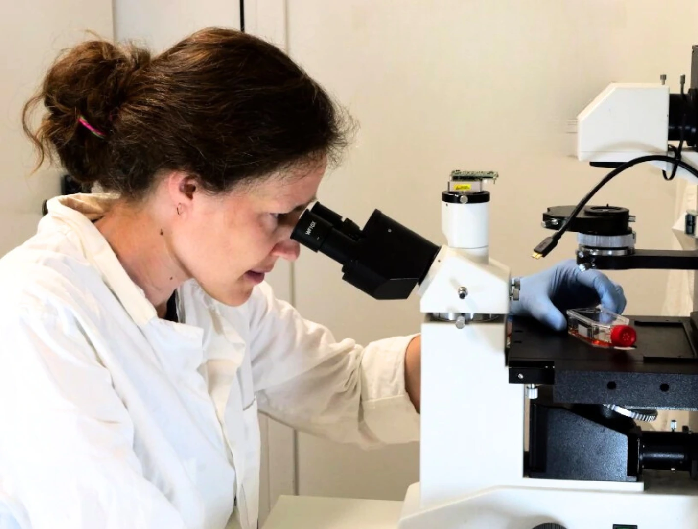
Need a microfluidic SME partner for your Horizon Europe project?
Rocker for organ-on-chip perfusion
The rocker for organ-on-chip perfusion drives medium back and forth through a microfluidic chip by tilting it. Two open reservoirs sit on the chip inlet and outlet, tilting raises one above the other, and gravity does the rest. There is no pump, no tubing and no contact between your medium and the instrument.
What separates it from a laboratory rocker is the input. You do not choose an angle and a speed. You enter the flow rate you want, in µL/min, or the wall shear stress you want, in dyn/cm², and the platform solves for the tilt trajectory that produces it.
Why a tilt angle is not a flow rate
A rocker takes an angle and an interval. Neither is a flow rate, and neither is a shear stress. What reaches your cells also depends on the channel cross-section, the reservoir spacing and the viscosity of your medium, so the same rocker setting gives different shear on a different chip.
You can recover the number afterwards. Published rocker work does exactly that, computing a mean flow rate and an average wall shear stress from a Poiseuille model and validating it by tracking fluorescent beads through the channel [1]. What that takes is a chip-specific model, and in careful work an independent measurement. That is the first problem: the number is yours to reconstruct, and to reconstruct again whenever the chip or the medium changes.
This platform does that work for you, and inverts it: you state the condition, the instrument solves for the trajectory. Programmed tilt control is not itself new. A 2025 pumpless system used programmable angular velocity to maintain unidirectional flow over a wide range of shear stresses [2], though that platform pursued a different goal from ours. What is new here is the interface, not the physics.
A rocker has a second problem, and it is the one people notice later. On a rocker sweeping at constant speed, flow follows the sine of the tilt angle: zero when the platform-stage is level, peak at full tilt, back to zero. A rocker setting computed to give 0.1 dyn/cm² has been measured to span roughly 0.04 to 0.29 dyn/cm² across its cycle [1]. So the number in your methods section is an average over a condition your cells never actually experience. This platform shapes the trajectory to hold the setpoint instead of sweeping through it.
How the tilt trajectory is computed
Three quantities set the flow through a gravity-driven chip: the height difference between the two liquid surfaces, the hydraulic resistance of the channel and the viscosity of the medium. The rocker for organ-on-chip perfusion sets the first through the tilt. It takes the second from the chip library or measures it on the chip in front of it. You supply the third.
As medium transfers from the high reservoir to the low one, the two levels close on each other and the driving head falls. The rocker for organ-on-chip perfusion keeps tilting to replace the head it has spent, which is what keeps the setpoint from decaying through the half cycle. When the tilt budget runs out, the platform reverses and the cycle repeats the other way. A high setpoint spends that budget quickly.
What the rocker for organ-on-chip perfusion computes and what it does not measure
This matters enough to state plainly. There are four different quantities in play, and they are not interchangeable.
- The commanded tilt angle, which the rocker for organ-on-chip perfusion controls directly
- The driving head, which follows from the angle and the reservoir geometry
- The flow rate and wall shear stress, which the platform computes from that head, the channel geometry and the viscosity you enter
- The flow actually delivered, which no part of this instrument measures
There is no flow sensor in the loop. The run log records the trajectory that was commanded and the values that were computed, not a measured flow trace. The model is the standard one for laminar flow in a rectangular channel.
The dominant uncertainty is the chip, not the mechanism. Flow rate scales with the cube of channel depth, so a channel 5 µm shallower than its drawing carries about 10 percent less than nominal. Wall shear stress is kinder. For a channel much wider than it is deep, wall shear equals the driving head times the channel depth divided by twice the channel length. Depth enters once rather than three times, so the same 5 µm deviation moves wall shear by about 3 percent while it moves flow by 10. If you need the flow rate right as well, let the platform measure the chip’s hydraulic resistance instead of taking the depth from the datasheet, or verify it with a flow sensor.
Worked example on a standard slide-format chip
The figures below are for a microfluidic ChipShop Fluidic 268 in PMMA, untreated: a single straight channel 2.5 mm wide and 150 µm deep, Luer ports 58.5 mm apart on a 75.5 × 25.5 mm slide, open reservoirs of 9 mm internal diameter, aqueous medium at 37 °C. Each line gives a setpoint, the wall shear stress it produces, and the hold time before the stage reverses.
- 43 µL/min, 0.62 dyn/cm², about 20 minutes
- 86 µL/min, 1.23 dyn/cm², about 8 minutes
- 129 µL/min, 1.83 dyn/cm², about 4 minutes
- 170 µL/min, 2.42 dyn/cm², about 2 minutes
- 210 µL/min, 2.99 dyn/cm², about 50 seconds
Reaching low shear stress
The instinct on a rocker is to turn the angle down. On any gravity-driven platform that is the wrong lever, and the literature shows why: at small tilt the driving head becomes comparable to the capillary pressure at the reservoir menisci, and measured flow departs from the hydrostatic model and plateaus [1]. On the reference chip a 1° tilt produces only about 10 Pa of head, the same order as the meniscus effects working against it. Below roughly 5° the computed number stops meaning much.
Use geometry instead. Because wall shear is head times depth over twice the channel length, a shallower and longer channel lowers shear while the tilt, and therefore the head, stays comfortably high. At 10° on a 58.5 mm chip the head is around 100 Pa, and a channel 50 µm deep and 250 mm long, serpentined onto a standard slide, lands near 0.1 dyn/cm². The chip library carries geometries chosen this way.
Use the rocker for organ-on-chip perfusion when
- You want defined, reportable perfusion without a pump or tubing
- Oscillatory or bidirectional flow suits your model, or is the condition you are studying
- You are running several identical chips and want them on one stated condition
- The culture sits in an incubator for hours or days
- You want to state a shear stress in a methods section rather than an angle and an interval
Use a pump instead when
- Your model needs sustained unidirectional flow
- Each chip needs its own independently controlled flow rate
- You need closed-loop control against a measured flow, not a computed one
- You need to image the cells during perfusion, since this stage moves. A perfusion pump is the right route
- You need arterial-level shear, which no tilting platform reaches on a microfluidic channel
Where the rocker for organ-on-chip perfusion came from
MIC develops the fluidic systems for NAP4DIVE, a Horizon Europe project building non-animal tools for testing nanoparticle drug delivery across the human blood-brain barrier [3]. The consortium needed a high-throughput blood-brain-barrier-on-chip, which meant perfusing many barrier chips at once, in an incubator, at a shear stress another partner could write down and repeat.
Pumps solve that one channel at a time. Every chip brings its own tubing and its own share of the pump, and external tubing is what limits how far a pump-based setup scales [1]. Rockers scale well and specify nothing. This platform came out of trying to get both.
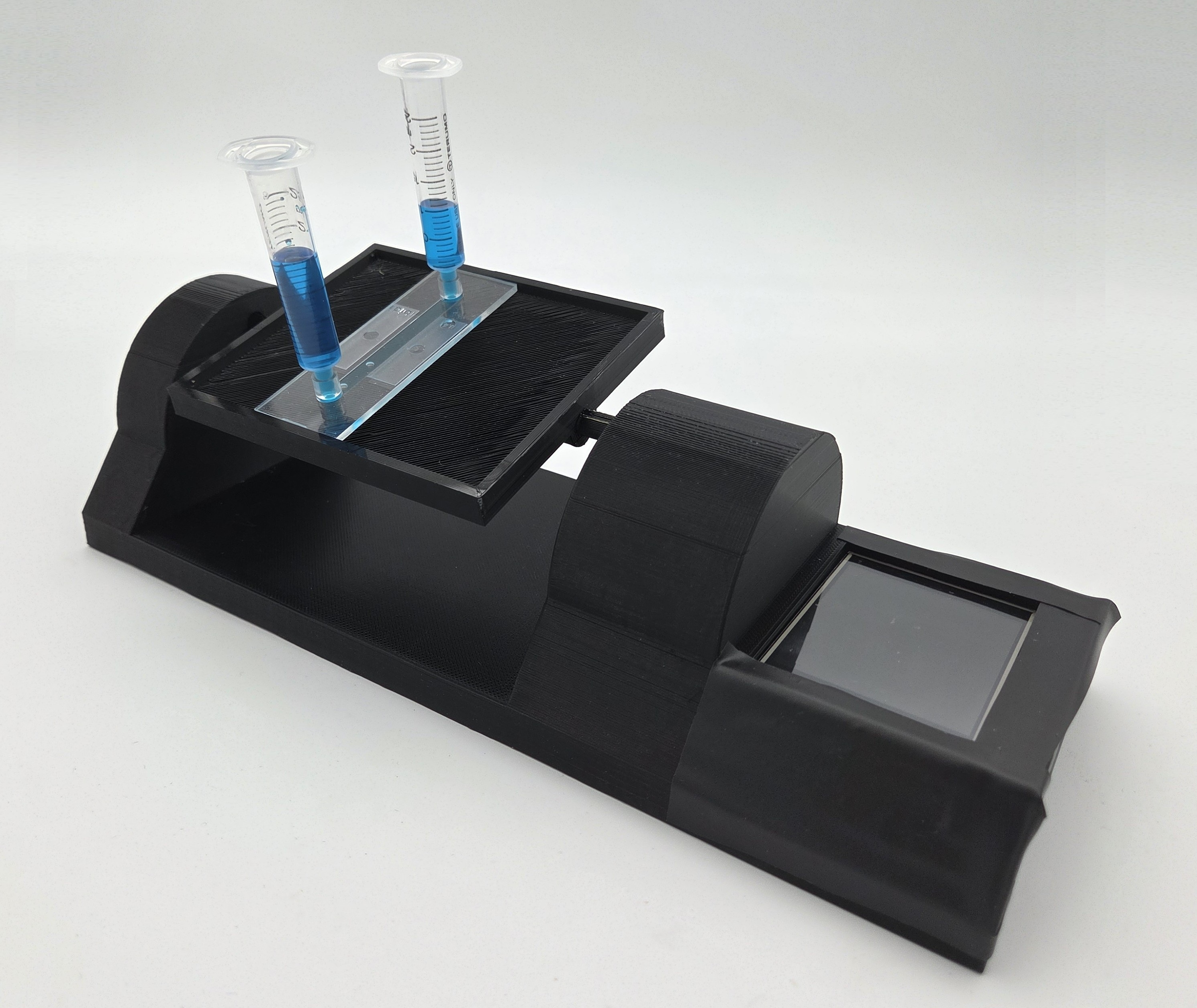
What's included
Tilting stage for three chips
Control unit with display
Chip holders
Reservoir holders
Windows control software
Chip and reservoir library
The stage is modular. Larger stages, and stages built around microplate footprints, are available on request. Every chip on a stage shares one tilt trajectory, so a stage carries one chip type with matched reservoir fills. Even then the chips are only nominally identical: at plus or minus 5 µm of channel depth on a 150 µm channel they differ by about 10 percent in flow and 3 percent in shear. Your medium never touches the instrument, so there is no fluid path to clean and no carryover between runs.
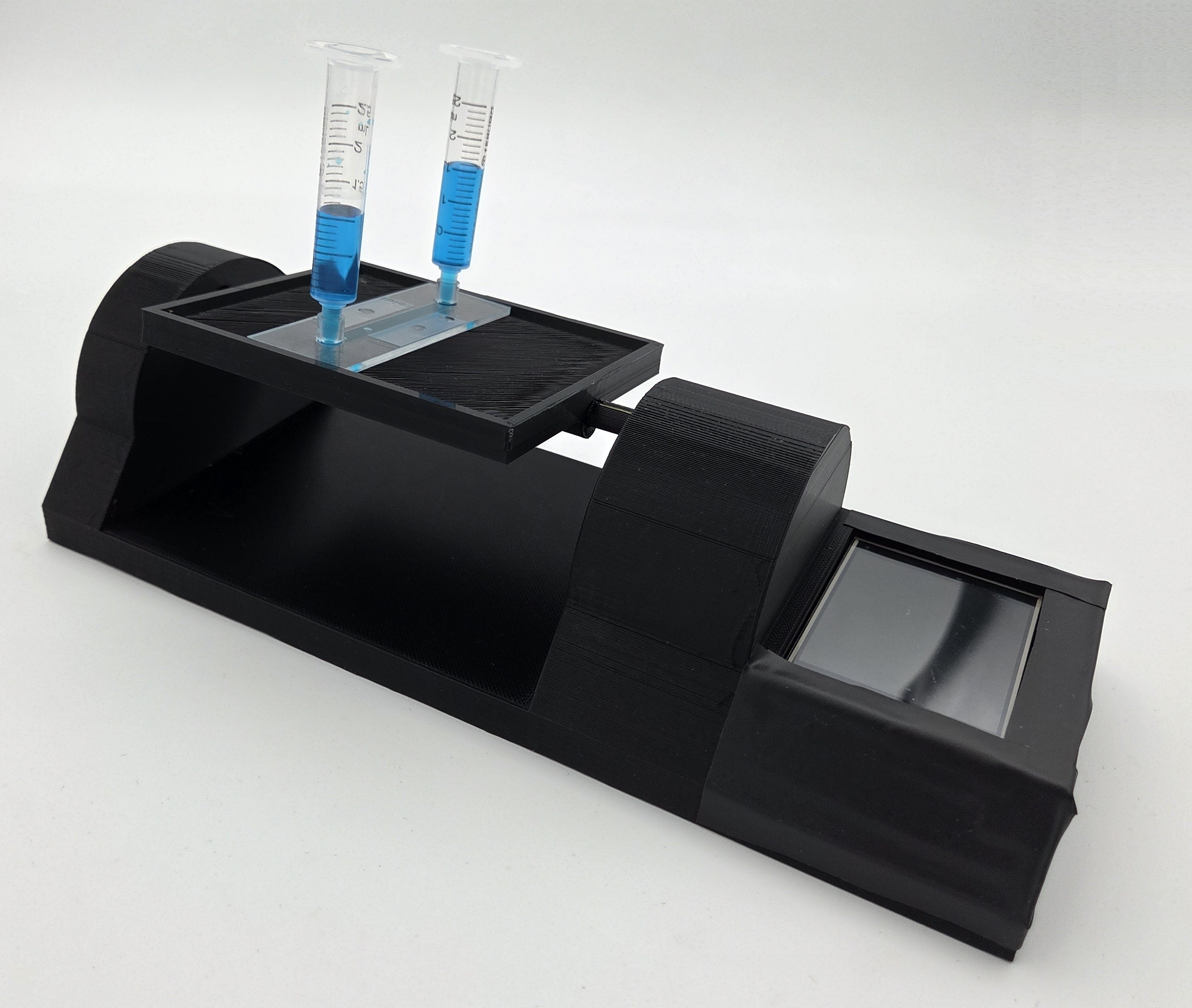
Application areas of the rocker for organ-on-chip perfusion
Where this platform is used:
- Parallel drug exposure in a plate format. Forty leak-tight gut tubules have been cultured in parallel on a single plate under rocker perfusion, with the response to two compounds followed over 125 hours [4].
- Barrier models perfused at a defined shear, with TEER measured repeatedly on the same plate rather than in an endpoint assay [5].
- Endothelial and vascular work where bidirectional flow is the condition under study. Rocker-induced bidirectional and pump-driven unidirectional flow are not equivalent: at matched average flow rates they produce different transcriptomic profiles, with changes after 24 hours in genes for immune cell migration, angiogenesis and matrix remodelling [1]. That is a reason to state your flow condition precisely, whichever one you choose.
- Chips with an ECM or hydrogel compartment, where the channel shear and the shear at the gel interface are different numbers and you need both. blood-brain-barrier-on-chip models sit here too.
- Long runs inside a CO₂ incubator, several chips at a time, with nothing crossing the door seal and no pump channel to buy per chip [6].
- Comparing your own rocker results against a pump-based dataset, with both expressed in the same units.
Technical specifications
Flow rate and wall shear stress depend on the chip and the reservoir, not on the platform alone. See the worked example above.
The rocker for organ-on-chip perfusion ships with the following specifications:
| Parameter | Value |
|---|---|
| Tilt range | ±30° |
| Angular resolution | 1° |
| Angular velocity | 1 to 10 ° /s |
| Recommended tilt for setpoints | 5° and above |
| Chips per stage | 3, slide format 75.5 × 25.5 mm |
| Other stages | Larger and microplate formats on request |
| Setpoint units | µL/min or dyn/cm² |
| Chip library | 50 references at launch, plus manual entry |
| User-made chips | Resistance measured on the chip |
| Wetted parts | None |
| Cleaning | 70% ethanol wipe, not autoclavable |
| Operating environment | 37 °C, 5% CO₂, up to 95% RH, continuous |
| Software | Windows, run log of commanded trajectory |
| Data export | CSV |
| Footprint | 30 × 15 cm |
| Compressed air | Not required |
Download the MIC Horizon Europe 2026/2027 Calls Calendar:
References
- [1] Vahdani N, Arora P, van Os L, Ackermann D, Mercader N, Guenat OT. Rocker or pump? Transcriptomic response of endothelial cells exposed to peristaltic pump-based unidirectional flow vs. rocker-induced bidirectional flow. Lab on a Chip 25, 5129 (2025). DOI 10.1039/d5lc00553a
- [2] Lino M, Persson H, Paknahad M, et al. A pumpless microfluidic co-culture system to model the effects of shear flow on biological barriers. Lab on a Chip 25, 1489 (2025). DOI 10.1039/d4lc00835a
- [3] NAP4DIVE, Non-Animal Platform for Nanoparticle-Based Delivery across the blood-brain barrier Interface with Vehicle Evolution. Horizon Europe, grant agreement 101155875. CORDIS project page
- [4] Trietsch SJ, Naumovska E, Kurek D, et al. Membrane-free culture and real-time barrier integrity assessment of perfused intestinal epithelium tubes. Nature Communications 8, 262 (2017). DOI 10.1038/s41467-017-00259-3
- [5] Nicolas A, Schavemaker F, Kosim K, et al. High throughput transepithelial electrical resistance (TEER) measurements on perfused membrane-free epithelia. Lab on a Chip 21(9), 1676-1685 (2021). DOI 10.1039/d0lc00770f
- [6] Wang YI, Shuler ML. UniChip enables long-term recirculating unidirectional perfusion with gravity-driven flow for microphysiological systems. Lab on a Chip 18(17), 2563-2574 (2018). DOI 10.1039/c8lc00394g
- [7] Busek M, Aizenshtadt A, Koch T, et al. Pump-less, recirculating organ-on-a-chip platform. Lab on a Chip 23(4), 591-608 (2023). DOI 10.1039/d2lc00919f


Funding and Support
This project has received funding from the European Union’s Horizon research and innovation program under HORIZON-HLTH-2024-TOOL-05-two-stage, Grant agreement number 101155875 (NAP4DIVE).
About the author

Savitashva Shringi, PhD
R&D engineer, Microfluidics Innovation Center
Savitashva holds a PhD from the École normale supérieure (ENS), with doctoral research carried out at the ENS and at the CIRB, Collège de France, where he worked on an in vitro vascularised dermal model under dynamic flow. At MIC he works on the engineering side of organ-on-chip: chip design, CAD and laminar flow simulation, microfluidic sensor integration, and dynamic cell culture. Much of that work is translating a biological requirement into an engineering specification.
Products & Associated Accessories
FAQ: Rocker for organ-on-chip perfusion
What is the rocker for organ-on-chip perfusion?
It is a tilting platform that perfuses microfluidic cell culture chips using gravity instead of a pump. Two open reservoirs sit on the chip inlet and outlet, and the platform tilts to move medium between them. You set a flow rate in µL/min or a wall shear stress in dyn/cm², and the platform computes the tilt trajectory that produces it.
How is this different from a laboratory rocker?
A rocker takes an angle and an interval as its input. You can work out the resulting flow and shear afterwards, and published rocker studies do, using a Poiseuille model validated against particle tracking [1]. But it is chip-specific work you have to redo whenever the geometry or the medium changes, and a rocker sweeping at constant speed also lets the shear swing widely across the cycle. This platform takes the condition as the input, solves for the angle, and keeps tilting through the half cycle so the setpoint does not decay as the reservoir levels equalise.
What flow rates and shear stresses can I reach, and how do I get low shear?
On a standard slide-format straight channel 2.5 mm wide and 0.15 mm deep with reservoirs 58.5 mm apart, setpoints run from about 43 to 210 µL/min, which is 0.62 to 3.0 dyn/cm². Lower shear comes from the chip, not from a smaller angle. Wall shear equals the driving head times the channel depth divided by twice the channel length, so a shallower and longer channel lowers shear while the tilt stays high. A 50 µm deep, 250 mm long serpentine on a standard slide reaches roughly 0.1 dyn/cm² at 10°. Arterial shear, above about 10 dyn/cm², is not reachable by tilting a microfluidic chip at all.
There is no flow sensor. What does the platform actually know?
It knows the angle it commanded, and it computes the head, the flow and the shear from that angle, the chip geometry and the viscosity you enter. It does not measure delivered flow, and the run log records the commanded trajectory and the computed setpoint rather than a flow trace. The model is the standard laminar one, so the uncertainty sits almost entirely in the chip. Flow scales with the cube of the channel depth and wall shear only with the first power, which is why a 5 µm depth deviation shifts flow by about 10 percent but shear by about 3. Letting the platform measure the chip hydraulic resistance removes most of that for the flow figure.
If I change the setpoint, what else changes?
The reversal period, and you need to design around it. A higher flow spends the tilt budget faster, so on the reference chip 43 µL/min holds for about twenty minutes per half cycle while 170 µL/min holds for about two. Comparing those two conditions changes shear magnitude and reversal frequency at the same time, and a difference in your readout could come from either or from their interaction. If shear magnitude is the variable you are testing, hold the reversal period constant by adjusting reservoir volume or chip geometry, and say in your methods which one you fixed.
Does the flow reverse, and what does that mean for my model?
Yes, it reverses, and that is a real experimental choice rather than a detail. Bidirectional flow is not a stand-in for physiological unidirectional flow: at matched average flow rates the two produce measurably different endothelial gene expression [1], and several groups have built special chip and motion designs specifically to obtain unidirectional flow from a tilting platform [7]. Bidirectional perfusion is appropriate when your model tolerates it, when oscillation is the condition you are studying, or when the assay has been validated under that waveform. If your model needs sustained one-way flow, use a pump.
How many chips can I run, which chips fit, and what about my own?
The launch stage holds three slide-format chips, 75.5 × 25.5 mm, and larger and microplate-footprint stages are available on request. The library ships with 50 commercial references. Every chip on a stage shares one tilt trajectory, so a stage carries one chip type with matched reservoir fills. Even then the chips are only nominally identical: at plus or minus 5 µm of channel depth on a 150 µm channel they differ by about 10 percent in flow and 3 percent in shear. For a chip you made yourself, enter the geometry by hand or let the platform measure its hydraulic resistance, which is the more dependable of the two.
Can I use it inside a CO₂ incubator, and can I image the cells while it runs?
Yes to the incubator. The platform runs continuously at 37 °C, 5 percent CO₂ and up to 95 percent relative humidity, and the launch stage is 30 × 15 cm, which fits a standard incubator shelf. Imaging is a different matter. The stage moves, so live imaging during perfusion is not possible here. For flow experiments that have to run on a microscope stage, a pump-driven setup is the right tool and we can point you to one.
Can MIC join our Horizon Europe proposal as a microfluidic SME partner?
Yes. MIC is a microfluidics SME and a regular beneficiary in EU consortia, including NAP4DIVE under Horizon Europe [3]. We take on the microfluidic engineering work package, build the prototypes and demonstrators, and help shape the technical parts of the proposal. Get in touch and let us know what the call is and where the fluidic gap sits.