Droplet detection and measurement in microfluidic channels
Author
Remigijus Vasiliauskas
Publication Date
February 08, 2018
Keywords
Optical imaging
droplet detection
Droplet Microfluidics
Electrical techniques
Need advice for your droplet detection methods?
Your microfluidic SME partner for Horizon Europe
We take care of microfluidic engineering, work on valorization and optimize the proposal with you
Introduction to microfluidic droplet detection methods
The history of microfluidics started in 1950 with the first inkjet printer, which used small amounts of fluids to print fine text precisely.
From that day onwards, microfluidics have evolved a lot, and now it is used to control fluids in volumes from 10-18 up to microliters [1], allowing costs to be reduced by reducing the volumes of rare or expensive materials used in experiments.
Next, droplet-based microfluidics has significantly influenced chemical synthesis and synthetic biology and even created new fields, such as high throughput single-cell analysis. Droplet-based microfluidics involves small droplet creation out of a fluid stream.
It provides the added benefits of removing Taylor dispersion’s effects and increased droplet transport ease [2]. Microfluidic droplets can include, isolate, and allow easy manipulation of reagents, particles, cells, or multicellular organisms [3].
The most significant advantage of droplet-based microfluidics over other droplet-based systems is the uniformity or monodispersity of the droplets. The coefficient of variation (C.V.) is used to measure the uniformity of the droplets and compare them from experiment to experiment. This number is usually below 5% and sometimes below 2% with microfluidics, which is very good compared to other droplet production techniques, such as batch mixers or sonicators, where a C.V. of 15% or more is acceptable.
Even though droplets prepared using microfluidics are more uniform, in some cases, an even higher droplet uniformity is needed, i.e., for drug encapsulation or mixing costly drugs. In such cases, special, active droplet monitoring and feedback systems are required, which can detect, measure, and regulate droplet size to avoid changes in size. The most challenging part, which requires the most work, is the droplet detection and size measurement.
Thus, this review will focus on the three main droplet detection and size measurement methods: optical imaging, laser or similar light-source-initiated detection, and electrical detection.
Optical imaging of droplets in microfluidic devices
In the case of droplet detection using optical imaging, the droplets are photographed in the microfluidic channels, and the images are analyzed in real-time or offline. The main advantage of real-time processing is regulating or stabilizing droplet size during the experiment. However, real-time analysis is minimal regarding how many images per second it can process, as it needs a lot of processing power.
Nevertheless, the speed could increase quickly with increased computer power and improved image processing algorithms. It was recently shown that real-time image processing could work up to 1000 Hz when using a line camera [4]. However, the real-time analysis of entire images and a droplet control using a feedback loop can work at up to 250 Hz when analyzing every droplet [4]. Even though the processing speed is not so high, the pressure pump is usually much slower.
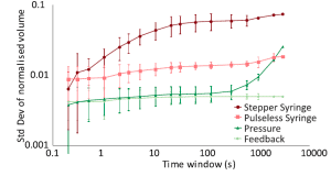
Thus, fast-response pressure pumps must be used to achieve 250 Hz controlled droplet production with the feedback system, as they have sufficient response time [5] compared to syringe pumps. At the same time, Crawford et al. [4] have shown that droplet size uniformity can be increased compared to other pumping methods using a feedback loop (Fig. 1).
The most exciting application of this method, next to droplet size measurement, is droplet sorting, depending on their content. It has been shown that using this method, droplets containing single cells [3] or microbes [6] can be sorted at up to 10 Hz rate with a fantastic accuracy of 90%.
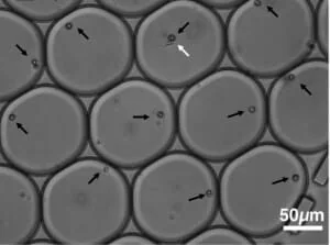
Without labeling the cells (Fig. 2), it was also shown that the system can separate empty droplets from occupied ones and distinguish between different cell types [3] that are contained inside the droplets. At the same time, this method allows the formation of the droplets and the forces acting on them to be st while exact control of droplet formation [7].
Another very interesting way of using the same optical imaging principle was discussed in a patent application [8] with the main application of droplet velocity measurement in a microfluidic channel. Here the droplet is exposed to three different color flashes in a very short time frame and the image taken is still in a single frame.
Thus, in one frame instead of one real image of droplet, one would get three images of the same droplet just illuminated with different light sources at different time frames. The detector then distinguishes the different colors, detects the droplet and calculates the droplet speed. This method could potentially work at higher speeds, however there is no such device yet on the market.
Even though there are a lot of applications of such system running in real time, in most cases it is being deployed in the offline regime for post-processing of images or videos containing droplets in a manual or automated regime. Software for automated droplet detection, measurement of their speed, size and size variation (C.V.) was developed [9] and is available as free at http://a-d-m.weebly.com/.
Even though the software has its limitations, it is a good start when automating your droplet measurement process and can save a lot of time if used correctly.
Laser (or LED) initiated detection of microfluidic droplets
Optical droplet detection in such systems is based on a directed light source entering the microchannels and detecting droplets. The droplets can be seen by exciting fluorescent material in droplets, catching back or forth scattered or even reflected light.
The main advantage of a laser-induced detection system is a very high detection rate, which detects very high droplet production rates. The disadvantage of the system is the lack of a baseline and calibration requirement for every batch of experiments.
The detector is usually placed in different positions depending on the detection system. To detect fluorescent light, the sensors are typically placed about 90 degrees from the incident light path while avoiding back or forward-scattered light. On the other hand, when working with big droplets (much bigger than the laser spot size), the detector is usually placed after the channel (fig. 3) to collect backscattered light. This is necessary for the droplets to block the light, indicating their presence, and while the signal is being processed, the droplet size can be acquired [10]. In case of reflected or backscattered light detection, the sensor is placed in the incident light path.
In most cases, such a system is used to detect droplets’ presence and measure droplet production frequency [11]. Still, it is not very difficult to upgrade the system to measure and automatically calculate the droplet or particle size [12-15].
In addition, the system allows the study of the cell’s internal structures (or droplets) as it is done in flow cytometry machines. However, the interpretation of results is still a challenge [16].
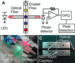
The system can be upgraded to detect several fluorescence wavelengths, which allows the detection and sorting of different cells or enzymes with varying fluorescence responses [16, 17]. For example, R. Cole et al. [17] have shown that it is possible to integrate several optical cables emitting different wavelengths, which can excite other fluorescent materials, the fluorescent light is detected, and droplets can be sorted according to the response.
The most common commercial devices using the laser detection principle are flow cytometers. Here, laser detection is used to detect droplets or cells, count them, measure size (forward scattering), sort cells, and analyze the insides of the cell (droplet) by using a fluorescence signal [16].
Electrical techniques for microfluidic droplet detection
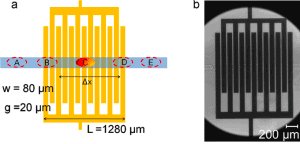
In the case of electrical techniques, multiple sensor arrays are directly integrated into the microfluidic chip. Most often, the capacitive (fig. 4) [18], electrochemical [19], impedance [20], and microwave [21] based electrical detection methods (sensors) are used.
When a droplet or microparticle passes over the contacts, it gives an electric signal, which is then recorded and analyzed. The advantage of this system is the possibility of sensing the content of individual droplets without any chemical or physical intrusion.
On the other hand, the main disadvantage is the difficulty of integrating electric contacts in the chip, which increases the price of the chip and prevents rapid prototyping. Compared with the techniques discussed earlier, where the detector is outside the chip and does not influence the chip itself, it is less universally applicable.
Nevertheless, it was shown that the droplet’s presence, speed, and size can be measured, avoiding cross-contamination [18] using this technique. Thus, the method shows high potential and the need for further work in the field.
Review done thanks to the support of the AutoDropProd project H2020-MSCA-IF-2017 – Marie-Curie Action: Grant agreement number: 796514
Author: Remigijus Vasiliauskas
Contact:
Partnership[at]microfluidic.fr

![]()

References
- G. M. Whitesides, “The origins and the future of microfluidics,” vol. 442, no. July, 2006.
- S. Mashaghi, A. Abbaspourrad, D. A. Weitz, and A. M. van Oijen, “Droplet microfluidics: A tool for biology, chemistry and nanotechnology,” TrAC – Trends Anal. Chem., vol. 82, pp. 118–125, 2016.
- M. Girault et al., “An on-chip imaging droplet-sorting system: A real-time shape recognition method to screen target cells in droplets with single cell resolution,” Sci. Rep., vol. 7, no. September 2016, pp. 1–10, 2017.
- D. F. Crawford, C. A. Smith, and G. Whyte, “Image-based closed-loop feedback for highly mono-dispersed microdroplet production,” Sci. Rep., vol. 7, no. 1, pp. 1–9, 2017.
- Elveflow, “OB1 MK3 – MICROFLUIDIC FLOW CONTROL SYSTEM,” www.elveflow.com, 2017. [Online]. Available: https://www.elveflow.com/microfluidic-products/microfluidics-flow-control-systems/ob1-pressure-controller/. [Accessed: 11-Jun-2018].
- L. Dong, D. W. Chen, S. J. Liu, and W. Du, “Automated Chemotactic Sorting and Single-cell Cultivation of Microbes using Droplet Microfluidics,” Sci. Rep., vol. 6, no. January, pp. 1–8, 2016.
- T. M. Moyle, L. M. Walker, and S. L. Anna, “Controlling thread formation during tipstreaming through an active feedback control loop,” Lab Chip, vol. 13, no. 23, p. 4534, 2013.
- D. Tracy, A. Weber, and P. Stokes, “Low cost optical high speed discrete measurements system,” WO 2014/194042 A2, 2014.
- Z. Z. Chong et al., “Automated droplet measurement (ADM): an enhanced video processing software for rapid droplet measurements,” Microfluid. Nanofluidics, vol. 20, no. 4, pp. 1–14, 2016.
- L. L. Tavlarides and B. Jae-Heum, “Laser Capillary Spectrophotometric acquisition of bivariate drop size and concentartion data for liquid-liquid dispersion,” 5,074,658, 1991.
- J. Li, J. Lindley-Start, A. Porch, and D. Barrow, “Continuous and scalable polymer capsule processing for inertial fusion energy target shell fabrication using droplet microfluidics,” Sci. Rep., vol. 7, no. 1, pp. 1–10, 2017.
- V. Trivedi, A. Doshi, G. K. Kurup, E. Ereifej, P. J. Vandevord, and A. S. Basu, “A modular approach for the generation, storage, mixing, and detection of droplet libraries for high throughput screening,” Lab Chip, vol. 10, no. 18, p. 2433, 2010.
- N. T. Nguyen, S. Lassemono, and F. A. Chollet, “Optical detection for droplet size control in microfluidic droplet-based analysis systems,” Sensors Actuators, B Chem., vol. 117, no. 2, pp. 431–436, 2006.
- X. Wu, C. H. Chon, Y.-N. Wang, Y. Kang, and D. Li, “Simultaneous particle counting and detecting on a chip,” Lab Chip, vol. 8, no. 11, pp. 1943–1949, 2008.
- S. W. Kettlitz, S. Valouch, and U. Lemmer, “Statistics of particle detection from single-channel fluorescence signals for flow cytometric applications,” IEEE Trans. Instrum. Meas., vol. 62, no. 7, pp. 1960–1971, 2013.
- H. M. Shapiro, Practical Flow Cytometry. 2003.
- R. H. Cole, Z. J. Gartner, and A. R. Abate, “Multicolor Fluorescence Detection for Droplet Microfluidics Using Optical Fibers,” J. Vis. Exp., no. 111, pp. 1–7, 2016.
- C. Elbuken, T. Glawdel, D. Chan, and C. L. Ren, “Detection of microdroplet size and speed using capacitive sensors,” Sensors Actuators, A Phys., vol. 171, no. 2, pp. 55–62, 2011.
- T. Abadie, C. Sella, and L. Thouin, “Electrochemical detection of droplet content in microfluidic devices: Evidence of internal recirculating convection within droplets,” Electrochem. commun., vol. 80, pp. 55–59, Jul. 2017.
- N. E. Yakdi, D. Bricault, F. Huet, and K. Ngo, “Detection and Sizing of Single Droplets Flowing in a Microfluidic Device by Impedance Measurement,” Procedia Eng., vol. 168, no. 0, pp. 1466–1470, 2016.
- G. Yesiloz, M. S. Boybay, and C. L. Ren, “Label-free high-throughput detection and content sensing of individual droplets in microfluidic systems,” Lab Chip, vol. 15, no. 20, pp. 4008–4019, 2015.
Check the other Reviews
FAQ - Droplet detection and measurement in microfluidic channels
What do individuals actually imply by droplet detection in a microfluidic channel?
Droplet detection involves reliably detecting every droplet flowing past a specific point on a chip and measuring size, speed, spacing, production frequency, and even clues to the content of droplets.
What is so important about the uniformity of droplet size?
The droplet microfluidics is frequently used as a high-throughput method of operating thousands to millions of small “micro-reactors. When droplet volumes vary, concentrations, incubation, and reaction kinetics become untidy, making them difficult to untangle afterward. One of the measures employed is the coefficient of variation (CV): in microfluidic droplet generation, it is usually below 5% and sometimes even below 2% in controlled systems. In contrast, more traditional droplet generation methods (batch mixers, sonicators) can yield CV values of 15% or higher.
What are the predominant ways of droplet detection?
Optical imaging (images with a camera): you literally draw pictures of droplets and count frames.
Laser or LED initiated detection (point detection): a beam of light is directed to droplets, where you are reading scattering, fluorescence, transmission, etc.
On-chip sensors: The chip had electrodes that detected capacitive, impedance, electrochemical, or microwave signals.
In optical imaging, how does reality time and distance measure droplets?
Computing, more than optics. Image processing requires sufficient horsepower to segment droplets, measure them, and issue a control signal quickly to count them. Literature reports indicate that real-time processing has been achieved with a line camera at approximately 1000 Hz, and full-image processing with a feedback loop at approximately 250 Hz when examining individual droplets. It is already fast compared to many of your experiment setups, but it is not free: it will require lean algorithms, good illumination, and stable optics.
You want closed-loop control over droplet size, and why is everybody still talking about pressure pumps?
Since response time is important. When your analysis is able to follow droplet formation at 250 Hz, but your pumping system is slow in responding, then the loop will be useless: the correction will be delayed, and you are chasing noise instead of drift. This is why fast-response pressure control is normally preferred to syringe pumps when tight, dynamic control is needed rather than only stable average flow.
Is droplet sorting not just droplet measuring?
Yes. Geometry is not the only way droplets are differentiated by imaging; what is in them (cells, microbes, occupancy) is also important. These rates have been reported to be up to 10 Hz, with approximately 90% accuracy in detecting droplets containing single cells or microbes. Certain systems can also isolate empty and occupied droplets, and different types of cells based on appearance or features/features. This is slow by the standards of many laser point-detection schemes, though it does cost you richer information per droplet.
Is there a credible way to measure droplet velocity with imaging without insane frame rates?
It is a smart one mentioned in the patent literature: turn on the same droplet with a series of colored flashes with very short time delays, then record a single composite frame. The droplet is repeated several times across the various channels of colour, and the difference in colour position provides velocity information. It is one of the concepts that are clear until one verbalizes them, and can theoretically operate at a higher effective speed than a typical frame-by-frame tracking.
And why should laser/LED-initiated droplet detection be used when cameras already have the ability to identify droplets?
A directed light source (laser or LED) perpendicular to the channel can measure droplets at very high production rates, often well beyond the maximum rates that full-frame image processing can adequately support. It is also the logical path to obtain fluorescence-based reads, multi-wavelength detection, or flow-cytometry-like analytics. The disadvantage is that you usually require delicate calibration, have to balance your experiments batchwise, and do not get as much information as an image provides.
Why and how does the placement of sensors matter?
In the case of fluorescence, detectors are often located at 90° to the incident beam so that forward/backward excitation light is avoided, which would otherwise contaminate the detector.
For large droplets (compared to the beam spot), you may place a detector after the channel to measure attenuation/blocking or forward scattering.
For reflected or backscattered signals, the sensor can be placed in the direction of incidence.
It reads like a small misalignment, but it dictates signal-noise, baseline drift, and the difference between your “droplet size” and the actual droplet size.
What do electrical droplet detection techniques measure?
Electrical techniques incorporate arrays of sensors on the chip and record the signal changes at droplet pass ages. Some of the common ones are capacitive, electrochemical, impedance and microwave sensing. The great advantage is that droplet content can be detected label-free, without any physical or chemical encroachment into the droplet. It is able to read the presence, speed and size and it does not cross-contaminate in some designs. The disadvantage is practical: to add electrodes, the chip complexity and cost are increased and it may slow down the process of rapid prototyping in comparison with external optical detectors.
Where would a microfluidic SME partner come in with this project (at least in Horizon Europe)?
The most critical engineering aspects of droplet detection systems include chip design, sensor integration, automation, data handling, validation standards, and the transformation of the concept into a reliable, reproducible prototype. This is exactly where an R&D-focused SME adds value. Their involvement helps translate ideas into tangible outcomes, strengthening the project’s credibility through realistic implementation plans, reduced technical risks, and a clear pathway toward exploitation.
At MIC, we support consortia through hands-on microfluidic engineering expertise, from chip design and fabrication strategies to stable droplet generation, detection module development, system integration, and rapid prototype iteration. We also contribute to shaping the proposal, including the work packages, milestones, KPIs, and impact and valorization strategies.
When an engineering-intensive WP is led by a partner with proven prototyping and fast-iteration capabilities, the entire project appears significantly more feasible and convincing to evaluators.