CO2 incubator-friendly microfluidic perfusion system for cell culture
Author
Lisa Muiznieks, PhD
Eve-Line Bancel, PhD
Publication Date
July 25, 2025
Keywords
CO2 incubator-friendly perfusion
Cell culture
Need advice for your microfluidic cell perfusion?
Your microfluidic SME partner for Horizon Europe
We take care of microfluidic engineering, work on valorization and optimize the proposal with you
Introduction
Cellular models of health and disease are standard tools used for research and preclinical drug discovery. However, traditional static models in culture flasks or dishes lack the range of physical cues relevant to the in vivo microenvironment. The addition of medium flow over cells in culture in a microfluidic chip offers the benefits of controlled nutrient exchange, a known and reproducible flow rate, flow profile, and precise shear stress (or avoidance of mechanical stress), as required by the assay.
Methods for adding perfusion can be based on various working principles, from gravity-driven approaches (e.g., rocking platforms or hydrostatic pressure) to pumping systems (e.g., syringes, peristaltic pumps, or pressure-driven flow controllers). Pressure-driven flow controllers enable precise and highly reproducible flow rate control, which is particularly important for maintaining low flow rates (down to 1 µl/min) for perfusion experiments that last days to weeks.
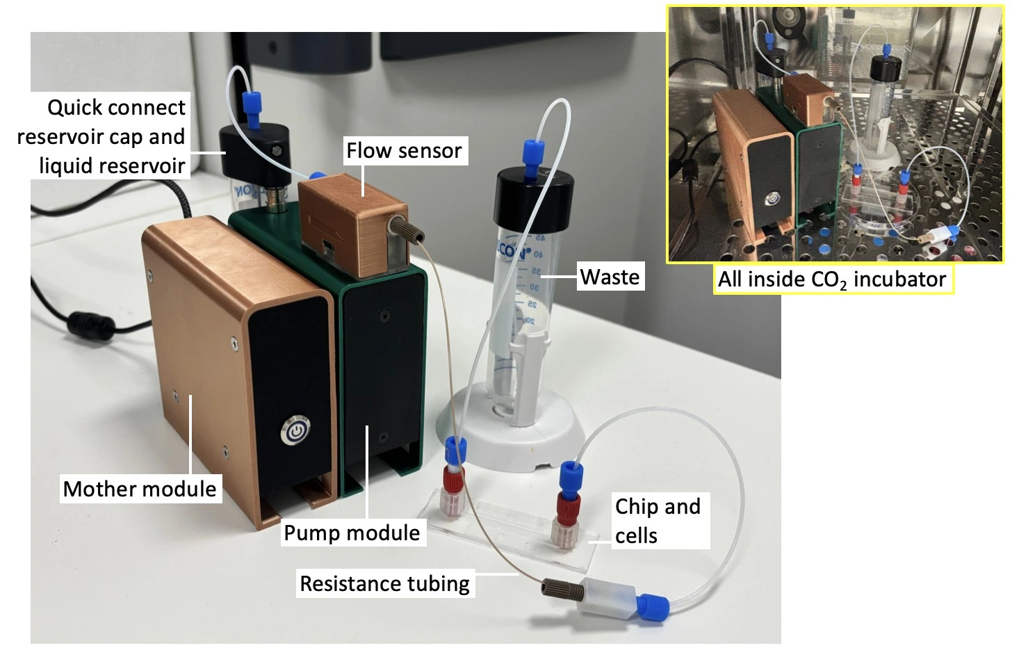
Here, we introduce a pump specifically adapted to cell perfusion and provide a detailed protocol on how to add flow to cells in culture. Our Caterpillar perfusion system for cell culture has been designed for straightforward setup, while ensuring high flow stability and facilitating parallelization. Its small volume means that it can be placed inside the cell culture CO2 incubator (or next to a live cell imaging microscope) for long-term experiments. This means the entire fluidic pathway can be kept inside the CO2 incubator, minimizing the addition of variables other than flow for your experiment.
This application note demonstrates the setup and use of the Caterpillar perfusion cell culture system in a CO2 incubator for 8 days, reporting the results of real-time measured flow rates and cell viability staining.
Applications
Cell perfusion on the microscale has wide applications in fundamental biological research, disease modelling, and the medical and pharmaceutical industry, such as:
- Live cell imaging (2D, 3D cultures)
- Microphysiological systems; organ-on-a-chip
- Shear stress studies
- Molecular transport
- Drug screening
The Caterpillar perfusion system for cell culture offers specific benefits of flow control, including:
- Stable control of flow rates down to 1 µl/min
- Full compatibility for use inside the CO2 incubator or a live cell imaging microscope chamber
- Features an integrated flow rate sensor
- Only needs a power supply and computer connection (no compressed air source is required)
- Snap together up to 6 modules for experiment parallelisation
- Snap-in liquid reservoir connection for ease of assembly
Setup
In this setup, a Caterpillar perfusion system for cell culture was used to push the medium in one direction through a microfluidic chip seeded with cells. This pump is combined with an integrated flow sensor that regulates the flow rate to maintain a stable profile inside the cell culture CO2 incubator. The pressure and flow rate can be recorded during the experiment using the dedicated software interface.
Materials
Hardware:
- Caterpillar pump (supplied with 1 quick-connect reservoir cap, 1 integrated flow sensor, and 1 piece of resistance tubing adapted to the targeted flow rate range)
- Microfluidic chip (e.g. µ-Slide I Luer, ibidi ®)
- Tubings (PTFE, 1/16” outer diameter; OD), fittings (see for details of connectors)
- 2 ✕ 50 mL Falcon tubes (optional: 1 ✕ standard reservoir cap)
- Blunt end metal needle (14G ✕ 5 cm, female Luer connection)
Reagents:
- Cells (e.g. U-251 MG GFP; 0.6-0.8 × 10⁶ cells/ mL)
- Medium: DMEM ([+] 4.5g/L D-Glucose; with 10% FBS, Penicillin/ Streptomycin (100 U/mL; 100 µg/mL)
- Phosphate buffered saline (PBS)
- Propidium iodide (PI) cell stain (75 µM)
Design of the chip
This experiment used a straight channel chip (µ-Slide I Luer 0.4; ibidi ®). The simple design and large internal geometry of the chip make it straightforward to fill, seed, and connect to the circuit. Its polymer coverslip base and microscope slide outer dimensions are ideally adapted for imaging, either as part of an endpoint staining protocol or for live cell imaging to monitor cell proliferation and morphology during perfusion.
µ-Slide I Luer 0.4 (ibidi ®) | Features |
Interface type | Female Luer |
Chamber volume | 100 µl |
Channel l ✕ w ✕ h | 50 ✕ 5 ✕ 0.4 mm |
Surface treatment | ibiTreat tissue culture treated |
Slide base | #1.5 polymer coverslip |
Quick start guide
Instrument connection and filling
This protocol first describes the assembly of the perfusion system for cell culture instrument in a Biosafety hood to maintain sterility. The setup is then transferred to the cell culture CO2 incubator, and the perfusion pump is connected to a power source and a computer to launch the software and start flow.
1. Select the appropriate size of falcon tube as the medium reservoir (e.g. 15 or 50 mL) and the corresponding tube cap. This experiment used a 50 mL Falcon tube.
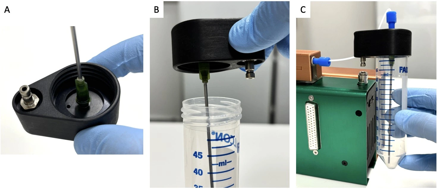
2. Connect a sterilized needle to the underside of the quick connect reservoir cap in a Biosafety hood to maintain sterility (see image below: Quick connect reservoir cap assembly).
3. Fill the reservoir with medium in a Biosafety hood and carefully screw on the quick connect reservoir cap with needle. Connect the quick connect reservoir cap to the Caterpillar perfusion pump via the quick connect port.
4. Attach tubing (1/16” ID PTFE) to the top of the quick connect reservoir cap with a ¼”-28 threaded connector and ferule and the other end to the inlet of the Caterpillar flow sensor.
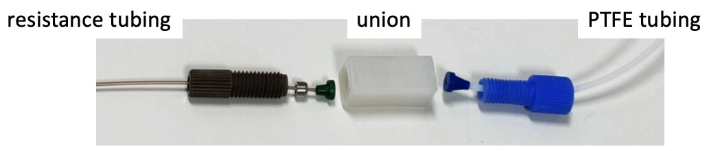
5. Connect the outlet of the flow sensor to the resistance tubing. To achieve the 1 µL/min target of this experiment, we used a 50 cm piece of tubing with 100 µm inner diameter.
6. Connect the outlet of the resistance tubing to a ¼”-28 threaded union, and add a length of 1/16” ID PTFE tubing to the outlet of the union.
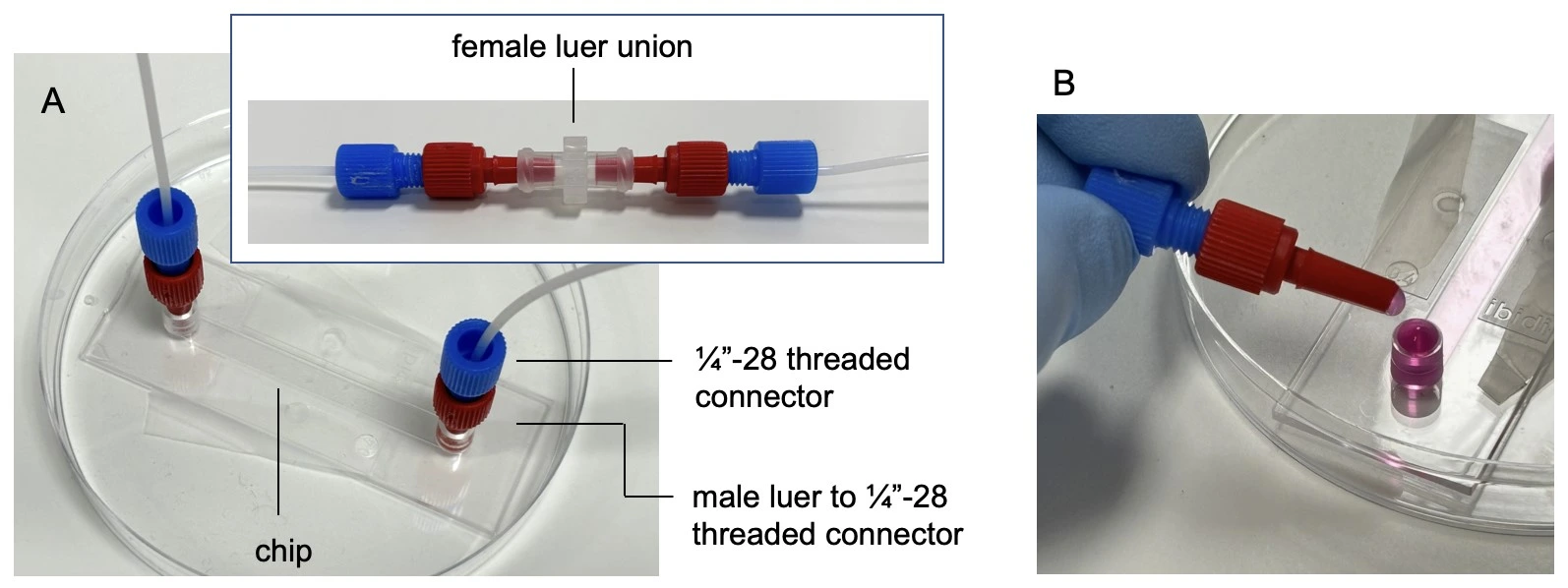
7. Connect the free end of tubing to a female Luer union (in place of the seeded chip for initial system filling) and connect the collection/ waste container (see image: Full fluidic setup).
8. Transfer the setup on a tray to the cell culture CO2 incubator.
9. Connect the pump module to a Caterpillar mother module and a power supply.
10. Connect the pump to a computer. Open the software and connect to the interface (see the User Guide for further details).
11. Start the Caterpillar pump and completely fill the system with medium.
Chip preparation and seeding
1. Add surface coating, if desired. Note that a commercially purchased “cell culture treated” surface is suitable for cell attachment without additional treatment, e.g., hydrophilized, collagen, ibiTreat, etc.
2. Prepare cell suspension as per standard protocols. Ensure all cell clumps are gently but well dissociated and count carefully. Use the suspension immediately.
3. Seed a µ-Slide I Luer 0.4 chip with a cell density of 0.6-0.8 ´ 106 cells/mL using a pipette. Position the pipette tip at the base of the inlet right at the entrance to the channel and apply slow and gentle pressure to avoid generating air bubbles.
4. Cover inlets/ outlets and leave 6-18 h in the CO2 incubator for cells to attach, or as needed for the application.
Chip connection to fluidic circuit
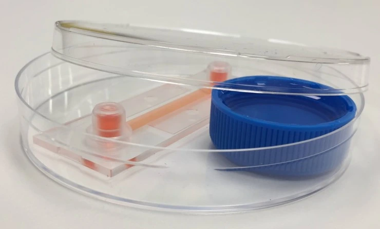
1. Tape the chip to a sterile petri dish for maximum stability and mark on it the direction of flow.
2. Remove the female Luer union. Connect the chip by touching the small droplet of medium at the tip of the connector to the meniscus of the medium at the chip inlet, to avoid trapping air.
3. Connect tubing to the outlet of the chip. Carefully wipe away any medium from the outside of the chip. Perform a visual inspection about 1 h after starting the experiment to ensure there are no leaks.
Experiment
1. Set desired flow rate on the Caterpillar perfusion pump interface, e.g., 1 µl/min.
2. Start flow and leave for the desired time, e.g., 8 days
3. Analyze results of the cell perfusion experiment, e.g. stain and image cells in the chip or perform downstream analysis of collected aliquots of medium as desired.
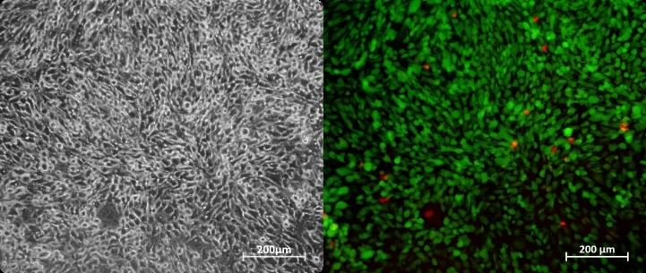
Results
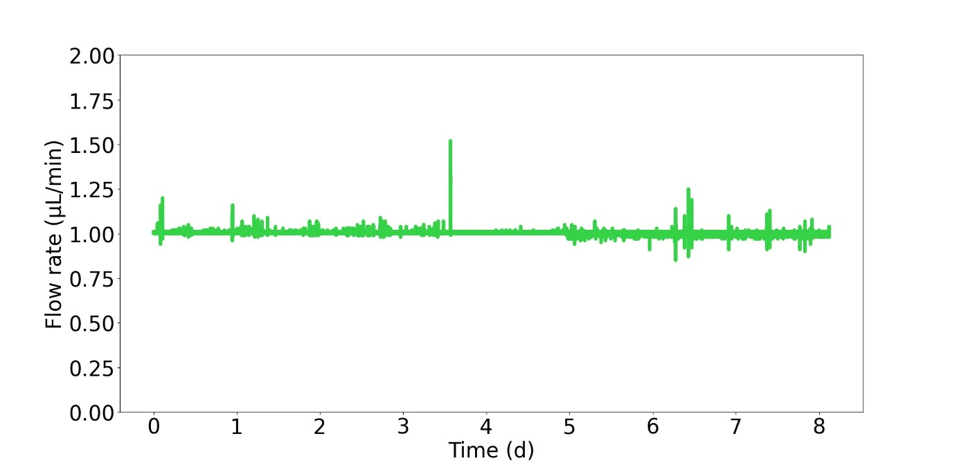
Cells were cultured in a microfluidic chip with constant perfusion (1 µl/min) using the Caterpillar perfusion system. After 8 days, cells were stained in the chip with propidium iodide (Fig. 1). The accuracy and flow profile of the perfusion pump were measured using the integrated flow sensor controlled via the interface.
The profile obtained was very stable, with amplitude peaks corresponding to external interventions (such as opening the cell culture CO2 incubator door).
More tips included in the Application Note PDF!

Acknowledgements
This application note has received funding from the European Union’s EIC Pathfinder Open program under the HORIZON-EIC-2022-PATHFINDEROPEN-01 Programme, grant agreement no. 101099719 (THOR).
This application note was written by Lisa Muiznieks, PhD, and Eve-Line Bancel, PhD.
Published on July 20255
Contact: Partnership[at]microfluidic.fr
Check the other Application Notes
FAQ - CO2 incubator-friendly microfluidic perfusion system for cell culture
Q1. What problem does an “incubator-friendly” perfusion system actually solve?
A setup like this keeps media flowing smoothly within a regular CO₂ incubator – held at 37 °C, around 5% CO₂, and high moisture levels – so cells stay put. Shifting them to a separate pumping station isn’t needed anymore. Because everything runs in one place, warmth and acidity hold steady. Less physical interference means gentler conditions for delicate cultures. Extended feeding cycles happen with minimal mechanical strain on the tissue. At the same time, exposure to outside germs stays limited.
Q2. What are the core building blocks of such a setup?
A compact flow driver (typically a pressure controller or low-pulsation pump) that tolerates 37 °C and humid air; sterile media reservoir with 0.22 µm vent filter; gas-permeable or gas-tight microfluidic chip (PDMS, COC, glass); bubble trap/degasser; sterile tubing and quick-disconnects; optional inline flow/pressure sensors and waste bottle with backflow protection. The full footprint usually fits on a single incubator shelf.
Q3. What flow ranges and shear stresses are realistic for adherent cells?
A typical range – say, between 0.5 and 50 microliters per minute per channel – covers needs for a broad set of mammalian cell types. Starting from fluid dynamics basics, wall shear stress in straight rectangular passages is approximated by τ ≈ 6μQ/(w h²). Take water-like viscosity at 0.8 millipascal-seconds, width near half a millimeter, height around one-tenth of that, plus a modest flow rate of 5 μL/min – the result lands just under 0.5 pascals, roughly 4.8 dynes per square centimeter. That level generally doesn’t bother endothelial layers; even some fragile epithelial cultures handle it fine. Whenever working with delicate strains, staying below 1 pascal helps avoid unintended mechanical irritation, unless probing shear responses is the actual goal.
Q4. How do we keep pH and osmolality stable during long runs?
Avoid large air gaps by keeping cultures in sealed containers to limit evaporation—running on bicarbonate-based solutions? Then maintain a steady 5% CO₂ setting. Fresh supply lines can blend directly into the system, so long as dwell duration stays within bounds. If operating over seven days, bring fluids to temperature ahead of time and balance pH before use. Instead of halting delivery mid-run, exchange feed bottles without breaking sterility.
Q5. What about bubbles – how are they prevented and removed?
A first line of protection involves removing dissolved gases from fluids – through vacuum setups or membrane tools – and pairing that with sealed tubing to block re-entry. Following this, a barrier comes into play: positioning a water-repelling trap, rich in open space, before the device catches bubbles early. Curved channel edges and smooth widening guide emerging bubbles naturally away, thanks to subtle shifts in flow behavior. When equipment sits in moist heating chambers, ensuring that the warmed lines stay hotter than the surrounding air prevents tiny eruptions where warmth meets cool spots.
Q6. Which pumps work best inside an incubator?
Fans of pressure-based setups often point to quieter operation alongside steadier flow patterns – multiplexing slips in neatly, too. Sterility gains a quiet boost when mechanisms avoid direct contact with the fluid. Should syringe or peristaltic units enter the picture, temperature tolerance near body heat matters, along with resilience in muggy conditions. Keeping those pumps outdoors, so to speak, helps dodge moisture buildup inside enclosures. Tubing passes through sealed entries, delivering clean paths without inviting damp trouble. Unchecked condensation? It tends to wear down hardware faster while nudging calibrations off track.
Q7. How do we keep the system sterile for multi-day culture?
Autoclave or gamma-sterilize what tolerates it; otherwise, ethanol flush plus sterile PBS/media rinse. Use pre-sterilized disposable chips where possible, 0.22 µm filters on all gas vents, and aseptic quick-connects. Build a single-use fluid path (reservoir → tubing → bubble trap → chip → waste) to avoid turnaround cleaning between experiments.
Q8. What cell types and assays are a good fit?
Some tissues respond to shear stress – like lining cells in chips grown together, or barrier layers made from stem cells. Immune cells slipping through, low-oxygen shifts, energy use tracking, or timed drug delivery are often included in these setups. Watching movement in real time yields data, just as collecting released proteins, measuring resistance across layers, tiny probes detecting gas or acidity changes, and later gene and protein scans do.
Q9. How do we size reservoirs and plan media logistics?
A single channel runs at five microliters per minute over three days – roughly 21.6 milliliters total. Build in an extra fifth to third of that volume, to cover startup flow and sample draws. As more channels join, the need grows in proportion. Uneven reservoir levels can cause interference, so separate control paths help maintain balance across outlets.
Q10. Can we run live imaging while perfusing?
A clear trend shows up in two forms. One approach leaves everything inside the incubator and checks results by timed image captures. Another relies on a chamber right on the microscope stage, fed by brief tubing runs that match temperature, linked to a pump outside. When high-numerical-aperture lenses come into play, focus shifts toward how much space remains between lens and sample – chip depth matters here. Devices built on standard cover glass, around 170 micrometers thick, tend to hold up image quality better.
Q11. How do we validate that cells see the intended chemical profile?
A sudden spike of tracer – say, fluorescein – reveals how long fluid lingers, tracking movement through the system. Breakthrough patterns appear at the exit; they are recorded carefully and then weighed against models that blend flow and spreading. When molecules seep out gradually, collection occurs downstream at regular intervals, like clockwork. Knowing the space inside the channel plus the average travel duration helps reverse-engineer how much builds up. Should concentration shifts play a role, a T-shaped junction sets the stage, while cross-channel snapshots confirm what’s really happening at each location.
Q12. What does MIC actually provide – and how fast?
A typical project begins with crafting bespoke microfluidic chips – using PDMS, COC, or glass – followed by incorporating pressure-based or mixed-mode fluid management. Integration of bubble-removal features and sensing elements follows, leading to a fully functional perfusion system ready for use in incubators, complete with standard operating procedures. Early alpha versions are often available within weeks, allowing room for successive refinements. Working as a small enterprise woven into multiple EU research networks, collaboration on proposal sections is common, alongside support in lowering technical risks during validation phases. Experience shows that when included in grant applications, chances of approval tend to run about twice the average rate seen in similar funding rounds.
Q13. Any common failure modes – and quick fixes?
A shift in flow can stem from reservoir back-pressure – best addressed by calibrating pressure control to match the incubator’s air. Reusable connectors may introduce gradual contamination; switching to disposable parts reduces that risk. Bubbles forming slowly on water-repelling surfaces? Try plasma exposure or opt for materials that attract water. When cell detachment occurs, consider adjusting τ, testing different surface treatments like collagen or fibronectin, and modifying startup routines – beginning with lower flow rates before increasing gradually.
Q14. How do we scale to many parallel channels?
Start each setup with pressure manifolds that include individual valves and integrated flow sensing – one route among several. Alternatively, pick a multiplexed bar-and-plate design with common inlet lines, while ensuring hydraulic resistance remains balanced across paths. Target consistent delivery: aim for under 10% variation in flow between channels at the desired throughput. When passive tuning falls short, slip small corrective restrictors into each leg. Another fix? Stabilize output using feedback-controlled actuators regulated by real-time deviation signals.
Q15. What documentation ships with a MIC system?
Starting with assembly protocols, each step follows a strict cleaning routine; different cells require different τ settings, laid out clearly by type. Priming comes next; removing bubbles is handled through gradual pressure shifts. Calibration data for flow resistance (Q – ΔP) are presented on simplified sheets tailored to specific setups. Computer-aided designs for chip mounts and fluid networks are updated regularly. Upkeep follows timed checklists, adjusted based on use. Example workflows? There are sample runs included – like a three-day membrane test or a weekly tissue-perfusion cycle – using baseline values that have already been tested.