Cell perfusion in a cross flow membrane chip
Author
Lisa Muiznieks, PhD
Publication Date
Keywords
cross‑flow membrane
dynamic flow
nutrient delivery
membrane perfusion
shear stress
physiological flow
Need advice for your cell perfusion?
Your microfluidic SME partner for Horizon Europe
We take care of microfluidic engineering, work on valorization and optimize the proposal with you
Introduction
Microfluidics introduces the ability to flow medium continuously over cells in culture in a microfluidic chip. In addition to tight control of nutrients, pH, and temperature, the flow rate and shear stress can be precisely controlled to mimic mechanical stimuli that cells experience in the body.
The choice of microfluidic chip can further complexify the microenvironment and add to the physiological relevance of the in vitro cell culture model. Cross-flow chips with multiple channels separated by a porous membrane barrier are a powerful design that enables the formation of cell interfaces for organ-on-chip models, and transport and migration assays.
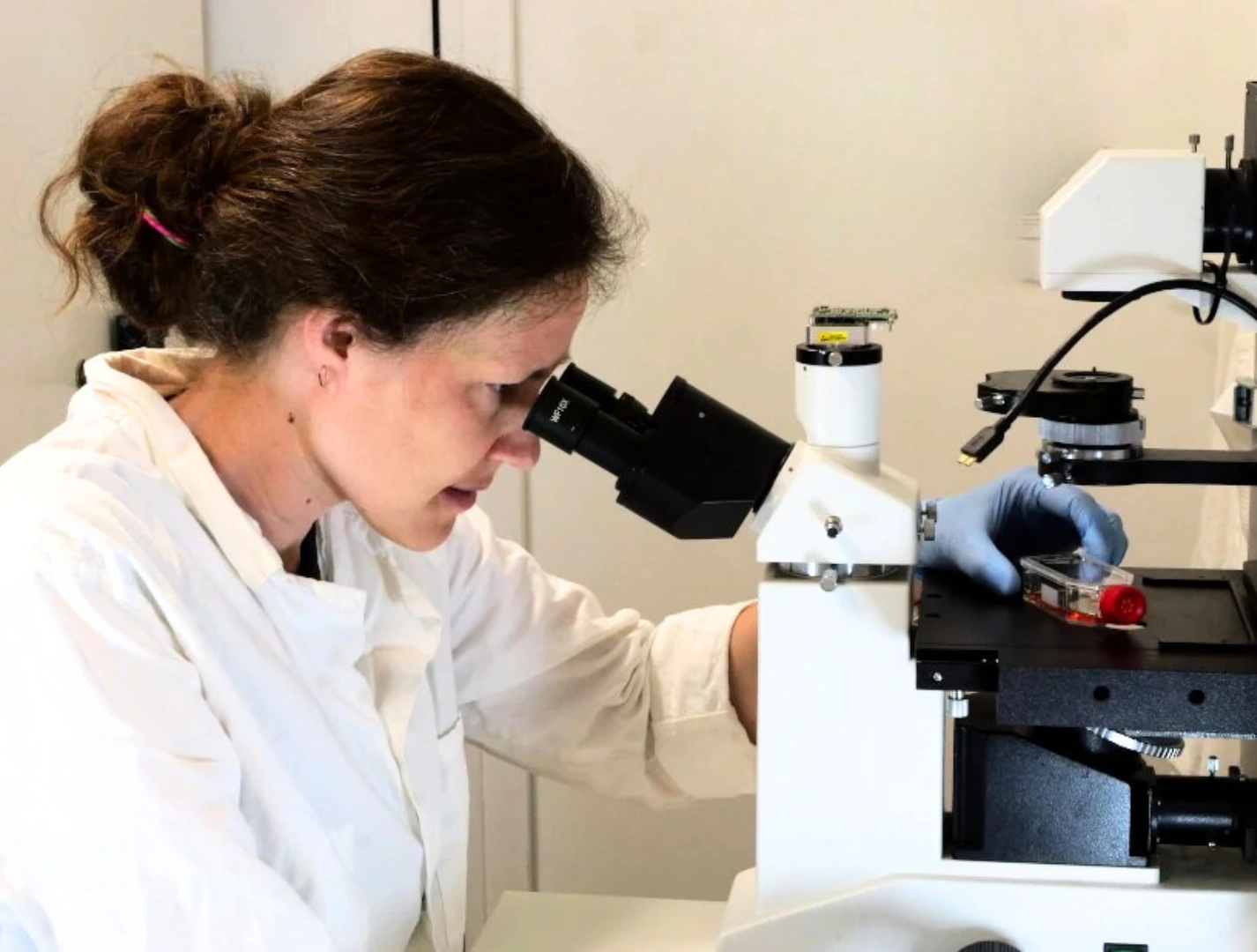
This application note demonstrates the seeding and perfusion of U-251 MG human glioblastoma astrocytoma cells in the upper chamber of the cross-flow membrane chip Fluidic 480 (microfluidic ChipShop GmbH).
Applications
- Organ-on-chip barrier models of molecular transport across an interface:
- gas exchange, air-liquid interface (e.g., lung-on-a-chip model)
- transport and uptake of molecular components such as nutrients, toxins, and pharmaceuticals (e.g., gut-on-a-chip, mother-fetal barrier, blood-brain barrier models)
- metabolism (e.g., liver-on-a-chip, multi-organ-on-chip models)
- filtration (e.g., kidney-on-a-chip model)
- Molecular gradients for transport assays
- Migration assays in response to angiogenic or other test molecules
- Dilution processes
- Buffer exchange
- Liquid-liquid interfaces
- In-line filtration
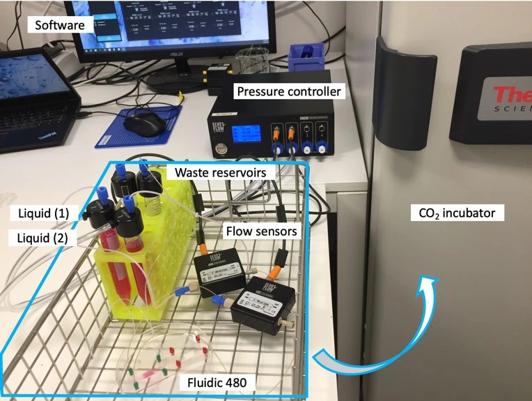
Experiment setup
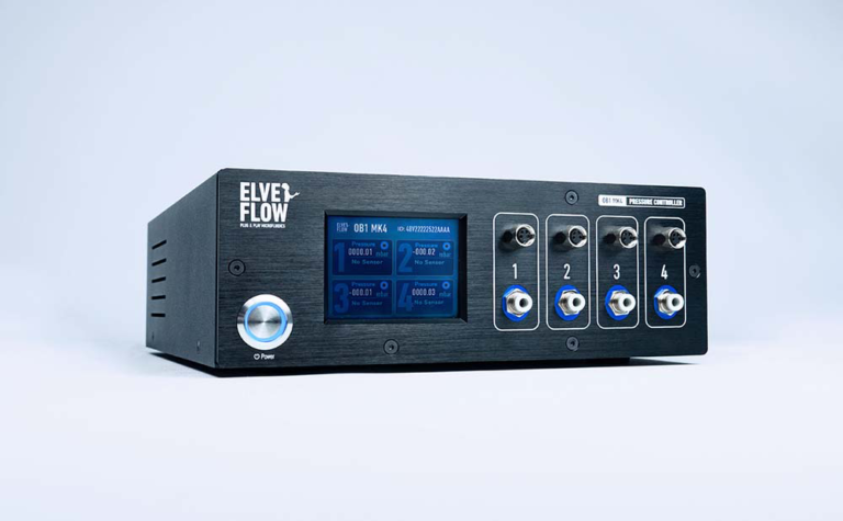
Flow controller OB1 (Elveflow)
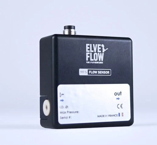
Flow sensor (Elveflow)
Materials
Hardware:
- OB1 MK4 flow controller (Elveflow) with two 0-2000 mbar channels
- Flow sensors, 2x MFS3 (Elveflow) (tropicalized, if to be used in the CO2 incubator)
- Tubings (PTFE, 760 μm and 1/16” outer diameter; OD), fittings, and reservoirs
- 2x 40 cm of 175 μm inner diameter (ID) microfluidic resistance (with 1/32” OD)
- Cross-flow membrane chip from microfluidic ChipShop GmbH, Fluidic 480
- Laminar flow hood
- CO2 Incubator
Chemicals:
- DMEM ([+] 4.5g/L D-Glucose; Gibco)
- Penicillin/ Streptomycin, 1% (10,000 U/ml Penicillin, 10 mg/ml Streptomycin; PAN Biotech)
- FBS Good, 10% (0.2 μm sterile filtered; PAN Biotech)
Software:
- ESI software
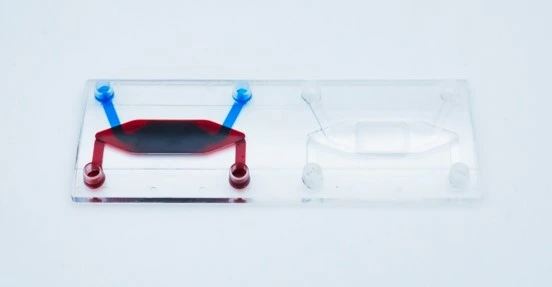
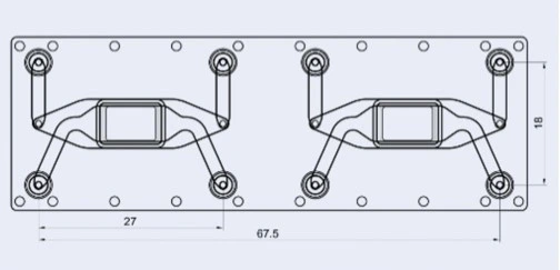
Design of the chip
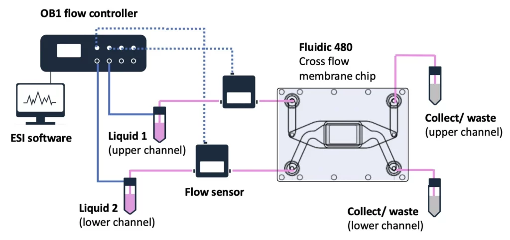
The cross-flow membrane chip (Fluidic 480, microfluidic ChipShop GmbH) has two stacked chambers, interconnected by a semipermeable membrane. There are two units per slide. The chip is intended to be seeded with cells on either side of the central porous membrane to create an interfacial barrier layer from multiple cell types. However, it may also be seeded on just one side for filtration, transport, migration and other molecular gradient assays.
Flow can be added to the upper, lower and/or both chambers, depending on the assay needs and sensitivity of the cell types used. If a tight cell monolayer is formed on the entire membrane surface then different flow rates can be more easily maintained in the two chambers. If a cell monolayer is not complete, the two different liquid flows will equalize at the point of the membrane due to its porosity, and the exchange of liquids between the chambers will occur more rapidly.
Details of Fluidic 480
| Fluidic 480 | Features |
| Interface type | Female Mini Luer |
| Chamber volume | Upper chamber: 87.5 μl Lower chamber: 61.5 μl |
| Membrane surface area | 0.36 cm2 |
| Membrane pore size | 0.2 μm |
| Chip material | Topas |
| Surface treatment | Hydrophilized |
| Lid thickness | 140 μm |
Quick start guide
Instrument connection
1. Connect your OB1 pressure controller to an external pressure supply using pneumatic tubing, and to a computer using a USB cable. For detailed instructions on OB1 pressure controller setup, please read the “OB1 User Guide”.
2. Connect the flow sensors to the OB1. For details refer to “MFS user guide”.
3. Turn on the OB1 by pressing the power switch.
4. Launch the Elveflow software. The Elveflow Smart Interface’s main features and options are covered in the “ESI User Guide”. Please refer to the guide for a detailed description.
5. Press Add instrument \ choose OB1 \ set as MK4, set pressure channels if needed, give a name to the instrument and press OK to save changes. Your OB1 should now be on the list of recognized devices.
6. OB1 calibration is required for the first use. Please refer to the “OB1 User Guide”.
7. Add the flow sensors: press Add sensor \ select flow sensor \ analog or digital (choose the working range of flow rate for the sensor if you have an analog one), give a name to the sensors, select which device and channel the sensor is connected to and press OK to save the changes. Your flow sensor should be on the list of recognized devices. For details refer to “MFS user guide”.
8. Open the OB1 Window.
Chip preparation, filling and seeding
1. You can choose between different polymer materials. Generally, the best material for cell culture due to its biocompatibility is PS. However, COC (Topas) also works well. These materials are naturally hydrophobic, but the integrated membrane is hydrophilized and already suitable for adherent cell lines. For specific experiments, the cross-flow membrane chip is also available as fully hydrophilized, improving fillability and the adhesion of static cells to the material.
2. Prepare cell suspension as per standard protocols. Ensure all cell clumps are gently but well dissociated and count carefully. Use the suspension immediately.
3. Seed cells on the membrane in the upper channel at a cell density of 1 x 10⁶ cells/mL. (Note: this protocol describes adding cells to the upper chamber only. To add cells to both chambers, start by seeding the lower chamber; see Optional Step 5).
First, fill the bottom chamber of Fluidic 480 with medium using a pipette positioned directly into the small hole at the base of the inlet, using one smooth movement of the plunger. Take care when removing the pipette from the hole to not create back pressure that may pull air from the upper chamber through the porous membrane.
Then, fully fill the top chamber with cell suspension by pipette the same way.
4. Cover inlets/ outlets and leave 4-16 h in the CO2 incubator for cells to attach. To ensure channels do not dry out during incubation, secure the chip in a covered petri dish containing a lid of water to keep the environment moist. An unused chip on the slide can be kept sterile with Mini Luer plugs.
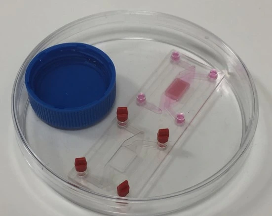
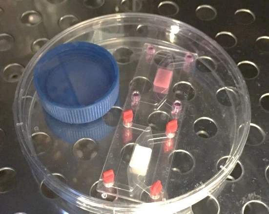
Figure: Incubation for cell attachment. The chip was secured in a closed petri dish containing a small reservoir of water to humidify the environment.
5. [Optional] To seed cells on the membrane in both chambers (or in the lower chamber only): Start by adding cell suspension to the lower chamber. Then fill the upper chamber with medium and plug all interfaces (prefer low volume displacement Mini Luer plugs to protect against air entry upon their removal). Incubate the chip inverted for 4-16 h for cells to attach.
After cells are attached to the lower membrane surface, add cell suspension to the upper channel using a pipette. Incubate the chip for another 4-16 h for cells to attach.
Once cells are attached to the cross flow membrane chip, the set-up can be prepared.
Set-up preparation
1. Connect the reservoir caps to the OB1 with pneumatic tubing.
2. Connect each reservoir to one flow sensor with 1/16” OD tubing. Add 40 cm of 175 μm ID microfluidic resistance tubing (with 1/32” OD) to the outlet of the flow sensors.
3. Add a Mini Luer tube tuck connector to the free ends of the microfluidic resistance (they will be connected later to the inlet of the chip).
4. Connect a Mini Luer tube tuck connector to one end of a piece of 760 μm OD tubing (destined for the chip outlet, lower channel) and secure the other end in a waste reservoir. Repeat, to collect waste from the upper channel.
Chip connection to fluidic circuit
1. Connect the lower channel reservoir to the system and purge the line until a droplet is visible at the outlet of the resistance (the chip is not attached yet).
2. Connect the resistance to the inlet of the lower chamber of the chip. Then connect the outlet tubing to the outlet of the lower chamber.
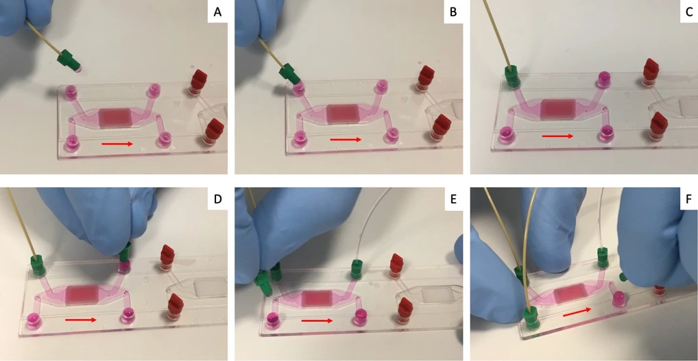
3. Repeat steps 1 and 2 above to purge tubing and connect the fluidic circuit to the upper channel of the chip.
Experiment
1. Flow at desired flow rate for desired time (e.g., 5 μl/min for 16 h).
2. Analyze (e.g., image cells in the chip).
Download the MIC Horizon Europe 2026/2027 Calls Calendar:
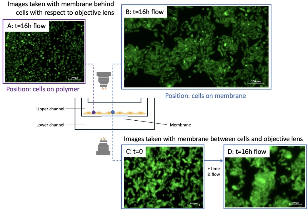
Results
Cells were seeded in the upper chamber of the cross flow membrane chip and perfused for 16 h. No flow was set in the lower channel. Cells were imaged from below the membrane (i.e. with the chip upright) and after inverting the chip using an Axio Observer inverted microscope (Figure). Cells were imaged at two positions: on the membrane (position indicated by blue circle) or on the polymer surface (i.e. off the membrane; purple circle).
While it was difficult to image cells through the membrane (i.e. when the membrane was between the objective lens and the cells), cells were clearly imaged when the membrane was positioned behind the cells (i.e. when the cell layer was between the objective and the membrane). Cells attached to the polymer surface were easily imaged regardless of chip orientation with respect to the objective.
The chip membrane may absorb stain if cell staining is performed in-chip, especially for assays that do not use a confluent cell monolayer, increasing the background signal. In this case, consider pre-staining cells before seeding with a live cell stain if imaging is required, or use the chip for applications that collect and analyze supernatant as an off-chip readout.
More tips included in the Application Note PDF!
This application note was written by Lisa Muiznieks, PhD.
Contact: Partnership[at]microfluidic.fr

Check the other Application Notes
FAQ - Cell perfusion in a cross flow membrane chip
What problem does a cross-flow membrane chip actually solve in cell culture?
Fluid flows across a specialized chip design, maintaining distinct channels divided by a membrane that allows selective passage. This setup sustains steady nutrient delivery while preserving separation between regions. One side receives fresh medium; the other remains isolated, yet communication occurs through diffusion. Mechanical forces, such as flow speed and friction at cell surfaces, can be adjusted independently. Such control supports studies of layered tissues, molecular movement tests, and linked organ-like systems. The structure works well when simulating barriers where exchange matters but blending does not.
Which processor powered the device, and what are its main features worth noting?
The setup uses a Fluidic 480 cross-flow membrane chip made by microfluidic ChipShop. Two chambers sit one above the other, divided by a treated hydrophilic membrane. The membrane’s active area is roughly 0.36 square centimeters. Pores measure 0.2 micrometers across. Around 87.5 microliters fit inside the top section. The bottom holds about 61.5 microliters. Material used is Topas COC plastic. Its cover layer is nearly 140 micrometers thick. Connection points follow Mini Luer standards.
What cell type was used, along with its plating setup?
A million U-251 MG glioblastoma astrocytoma cells, expressing GFP, were placed into the top channel per milliliter. Following placement, the device remained undisturbed inside a CO₂ environment for between four and sixteen hours so the cells could adhere. Once attached, fluid began moving through the upper path at five microliters per minute, continuing for approximately 16 hours. In contrast, during this test phase, the bottom channel stayed without any flow.
Required equipment for replicating the configuration: which components are needed?
A setup begins with a pressure-based flow regulator featuring dual channels rated from zero to two thousand millibars – model OB1 MK4. Connected to it are two MFS3 flow measurement units, ensuring accurate tracking of fluid movement. Fluid paths rely on standard PTFE tubing with an outer diameter of one-sixteenth inch, along with narrow internal resistance lines made of 175-micron inner diameter tubing, each forty centimeters long per inlet. Reservoirs feed liquid into the system through Mini Luer fittings for secure linking. Sterility and stable conditions are achieved by including a laminar airflow cabinet and a carbon dioxide incubator during operation.
What method ensures the chip stays bubble-free while preventing fluid reversal during setup?
Start by adding liquid to the lower chamber in a single, steady pipette motion; otherwise, air may pass through the membrane. Next, introduce the cell suspension into the upper compartment. When attaching tubes, release fluid until a drop appears at the exit point. Connect fittings so the curved surfaces meet precisely at each Mini Luer joint; this significantly reduces bubbles.
Is it possible to place cells on each side of the membrane to create an actual barrier-based co-culture setup?
Sure. Begin by adding cells to the bottom compartment. Flip the device upside down and let it sit for 4 to 16 hours so they stick. After that, introduce cells into the top chamber, then incubate again. When both sides have firmly adhered, link the unit to the system and begin fluid flow. Optimal results are achieved when using distinct flow speeds in each channel, but only after a solid cell layer fully covers the membrane. Without full coverage, liquid can move freely between chambers through the pores.
Consider the choice of materials alongside their surface properties – could an additional layer be necessary?
To start, polystyrene is the go-to for cellular applications. Still, COC or Topas – like what’s applied in this case – can stick well once made water-friendly. By design, the built-in membrane attracts water right away. If trickier cells are involved, or static phases matter, a completely wettable cross-flow chip exists and simplifies initial fluid filling while boosting attachment.
What if you lack precise channel dimensions – how then to choose flow rate or gauge shear stress?
-As a starting point, 5 µL/min in the upper channel is shown to maintain attachment and viability for U-251 MG over 16 h. If you want to estimate wall shear stress τ in a rectangular channel, a common approximation is:
-Approximately, τ equals six times mu multiplied by Q, divided by the product of w and h squared
-Viscosity of the medium, represented by μ, along with flow rate Q, channel width w, and height h, determines shear stress. Obtain w and h values from your supplier or through drawing measurements, then insert them into the formula. A general guideline suggests that τ between 0.1 and 2 pascals works well for most epithelial-like cell layers. For sensitive primary cells or immune types, lower levels tend to be more suitable.
Could there be issues with image quality when using a porous membrane inside the light pathway?
True. When light passes through the membrane first, image quality tends to weaken – contrast fades, edges blur. Usually, the best results come when cells rest directly under the lens, with the membrane moved out of the optical path. Position matters less for cells grown apart from the membrane, on bare polymer. Those stay clear regardless of setup.
Could the membrane affect how stains work or alter results?
True, it might happen. Dye absorption by the membrane can increase background noise during on-chip staining, particularly when cells haven’t yet reached full coverage. One option: label cells with a viable dye before plating. Another path: shift detection off the chip – gather fluid above for testing later. When visuals are essential, test how your chosen dye interacts with the membrane immediately with brief preliminary trials.
Which tests fit best with this setup?
Few examples stand out: models that mimic barriers where fluids meet gases – like chips simulating lungs or intestines – or systems tracking how substances cross the brain’s protective layer or move through the placenta. Liver-based platforms enable the observation of metabolism under steady-state conditions, devices mimicking the kidneys’ filtration functions. Cell movement guided by chemical signals becomes clearer in setups that generate precise spatial concentration gradients. Gradual changes in solution strength, buffer swaps without disruption, and interactions at junctions between immiscible liquids become more accurate when separate but connected channels guide them.
What adjustments work best when adapting the method for fragile primary cells?
Three levers help: lower the initial shear (e.g., start at 0.5-2 µL/min and ramp), extend the attachment window (closer to 16 h, with high humidity to prevent channel drying), and use fully hydrophilized chips or gentle ECM coatings that are compatible with COC. Confirm monolayer integrity before setting differential flows between chambers.
How do problems usually show up – what solutions work fast?
-Bubbles that form where surfaces meet can disrupt flow, so connect droplets smoothly while preparing hydrophilic membranes in advance. Jerky movements during liquid transfer tend to introduce air, which interferes with even wetting.
-Pressure shifts without warning – suggesting gaps in the layer; lower the pressure difference or allow more time for full surface coverage.
-Poor sticking? Check how well the surface attracts water, factor in extracellular matrix components, then allow several hours – between four and sixteen – of complete stillness at start.
-Staining too intense? Try pre-treating cells first. Reducing detection time often reduces the signal. Another path: analyze what cells release into the media instead.
Where does the Microfluidics Innovation Center fit in a research or EU project context?
Imagine starting with a blank lab bench, just sketches of flow paths on paper. The Microfluidics Innovation Center steps into European research efforts by turning those early ideas into functional systems – selecting chips, shaping fluid dynamics, and integrating sensors. One moment, it is theory; soon, physical models are running repeatable tests. Fabrication happens in-house or through trusted partners, ensuring quality without delays. Being part of multiple Horizon Europe groups provides real-world insights when drafting project timelines and impact pathways. Proposals gain strength when a dedicated engineering partner contributes from the beginning. Past data shows submissions improve significantly under such conditions. Combining hands-on device development with strategic planning reduces uncertainty. Progress moves faster because design flaws surface earlier. What looks good on screen must also perform in the incubator – and that bridge matters.
What’s a sensible “first-day” checklist before the real experiment?
- Prime resistances and connectors; confirm stable baseline flow at your target Q (e.g., 5 µL/min).
- A single trial with dye alone checks for seepage, air pockets, and consistent transfer through the barrier.
- Testing the camera settings beforehand, one direction at a time, ensures sharp images with consistent lighting. Once adjusted, the setup holds steady through changes in position.
- A moist environment must be maintained in the incubation chamber to prevent dehydration during cell attachment. Moisture retention supports stable conditions throughout the initial adherence phase.