Microfluidic pump flow profiles: a comparative review
Author
Celeste Chidiac, PhD
Publication Date
Keywords
Flow profiles
Syringe pump
Peristaltic pump
Pressure pump
Fluid recirculation

Need advice for your pump flow profile?
Your microfluidic SME partner for Horizon Europe
We take care of microfluidic engineering, work on valorization and optimize the proposal with you
Introduction
Controlling microfluidic pump flow is essential for biological assays, chemical analysis, and material synthesis applications. Different pumping systems can generate various flow profiles, each with unique characteristics suited to specific experimental requirements.
Microfluidic pump flow can be regular or irregular. The flow pattern of a regular flow is steady or pulsatile, whereas the flow pattern of an irregular flow is disturbed or oscillatory. For steady flow, a certain shear stress (τ) is produced. For pulsatile and reciprocating flow, cyclic change in the shear stress level is maintained, with a higher level for pulsatile flow than for reciprocating flow (Figure 1) [1].

Microfluidic pump flow manipulation strategies can be categorized as passive and active methods. Passive manipulation methods mainly rely on microfluidic design, microchannel geometry, and internal forces to affect liquid flow without the need for external forces or triggers. Examples of passive manipulation are hydrostatic pressure and capillary-driven flow. On the other hand, active methods utilize an external force field to generate flow, such as syringe, peristaltic, pressure, gear, electroosmotic, and centrifugal pumps.
Here’s an overview of microfluidic flow profiles generated by passive and active manipulation.
Download the MIC Horizon Europe 2026/2027 Calls Calendar:
Passive manipulation of microfluidic flow
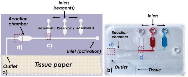
Capillary-driven flow
Flow profile: Passive flow driven by capillary action
Working principle: Fluids move through microchannels due to capillary forces, without the need for external microfluidic pump or pressure. Surface tension and channel geometry control the flow.
Characteristics/Considerations:
- No external microfluidic pump or power source required.
- Simple, self-sustained flow.
- Ideal for portable, low-cost devices.
- Limited to slow and steady flow rates.
- Difficulty controlling or adjusting flow once initiated.
- Flow is influenced by channel geometry, liquid properties (viscosity, surface tension), and the material wetting properties.
Applications:
- Microfluidic paper-based analytical devices (μPADs), lateral flow assays (e.g., pregnancy tests), and low-cost point-of-care diagnostics [2, 3].
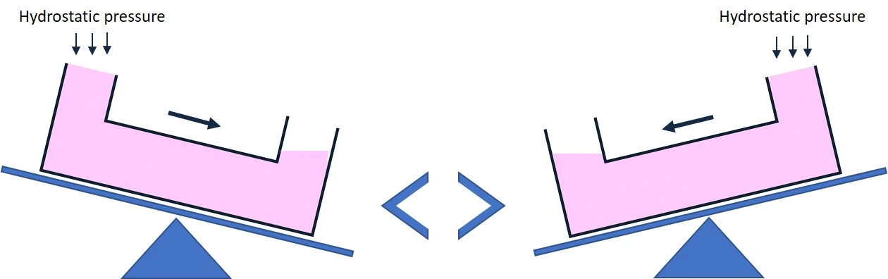
Hydrostatic pressure
Flow profile: Slow, laminar flow
Working principle: The hydrostatic pressure method is based on differences in fluid height to generate fluid flow through a microchannel.
Characteristics/Considerations:
- No external microfluidic pump or power source required.
- Passive flow is essential in applications where active components might introduce noise.
- Laminar flow suits applications requiring limited mixing.
- Can generate low flow rates only.
- Flow rate control is limited to fluid column height and liquid volume. Adjusting flow requires manual intervention.
- Flow decreases over time as the difference in height between the two reservoirs decreases.
- Flow is disrupted when adjusting reservoir height or refilling reservoirs.
- Flow rate can be controlled by a programmable rocking platform. In this case, the flow rate depends on the rocker speed and tilt angle.
Applications:
- Cell culture studies, disposable diagnostic devices, and diffusion-based experiments requiring a slow, steady, and laminar flow.
Active manipulation of microfluidic pump flow
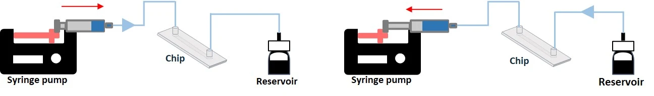
Syringe microfluidic pump
Pump flow profile: Oscillating, pulsatile.
Working principle: Syringe pumps can both push-in (infusion) and pull-out (withdrawal) fluid through a microfluidic channel using an electric motor pushing a syringe plunger at a set rate. With programmable syringe pumps, users can go beyond simple infusion and withdrawal operations and create customized pumping methods with simple to complex flow profiles.
Characteristics/Considerations:
- The accuracy is 0.25% max with near pulseless syringe pumps
- The flow rate is constant over time, even with varying microfluidic resistance.
- The syringe pump is suitable for precise flow control and low flow rates (µL/min to mL/min).
- Experiment length is limited by the syringe volume unless an infusion-withdraw syringe pump is used.
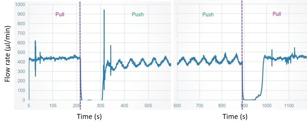
- Flow is disrupted when the syringe is empty and during push/pull transition.
- The flow rate is not monitored in real-time; calibration may be required.
Applications:
- Chemical reactions, microfluidic cell assay, drug delivery studies, or analytical measurements where slow reagent addition is needed [5].
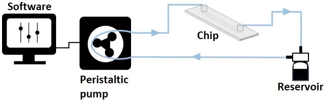
Peristaltic microfluidic pump
Pump flow profile: Pulsatile flow.
Working principle: Peristaltic pumps are versatile, efficient, and reliable. Fluid is pushed through a flexible tubing in the pump head by the compression and release of rollers in the peristaltic pump. Pressure is applied to the liquid within, causing it to be squeezed through the length of the tubing and controlling its speed.
Characteristics/Considerations:
- Flow is continuous.
- Can handle shear-sensitive fluids like biological samples.
- Fluid displaced volume is limited by the volume of the reservoirs in a non-recirculation setup.
- Continuous unidirectional fluid recirculation is possible with one reservoir as an inlet and outlet.
- The amplitude of pulsed or uneven flow may not suit all applications. However, this can be smoothed out with certain tubing configurations or additional dampeners.
- Flow control is not monitored in real-time and is less stable over time, requiring repeated flow rate calibration.
- Peristaltic pumps cannot reach low flow rates (less than 1 µL/min).
- Usually less accurate than syringe pumps and pressure controllers.
Applications:
- Ideal for applications that require continuous flow over long periods, such as perfusion in cell culture systems, or nutrient delivery.
- Ideal for handling chemicals, or hazardous materials, as the fluid remains isolated from the pump and is transported through disposable tubing [6].
Pressure microfluidic pump
Pump flow profile: A variety of flow profiles is possible: pulsatile, steady, stepwise, customized.
Working principle: Pressure-driven pumps control the pressure applied to a fluid reservoir, driving fluid through microfluidic channels.
Characteristics/Considerations:
- High precision and fast response to flow control.
- Flow rate control can be achieved with a flow sensor feedback loop.
- Suitable for both low and high flow rates.
- Continuous operation as long as the pressure source is stable.
- Fluid displaced volume is limited by the volume of the reservoirs in a non-recirculation setup.
- Continuous fluid circulation allows infinite looping of liquid (volume is not consumed).
- Bidirectional fluid flow in a recirculation setup, can be made unidirectional with the use of a valve system (check our automated recirculation system).
- Flow rate is influenced by changes in channel resistance or viscosity; thus, adjustments may be needed.
Applications:
- Droplet generation, rapid mixing, and cell-based assays where pressure changes allow dynamic control over the flow.
- Unidirectional recirculation for cell perfusion using a rotary valve, 3/2 valves, or check valves [7].
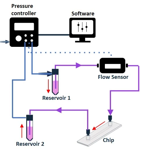
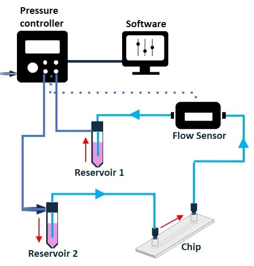
Figure 7: Recirculation setup with a pressure pump. The flow is bidirectional without the use of a valve system.
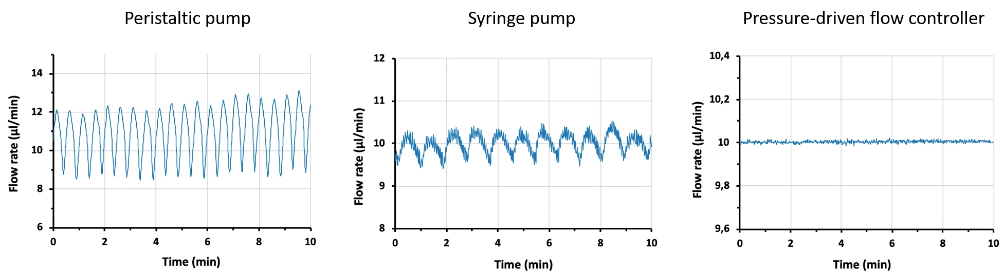
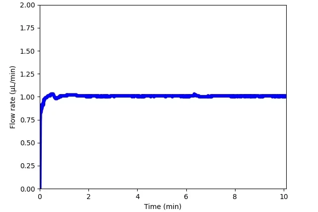
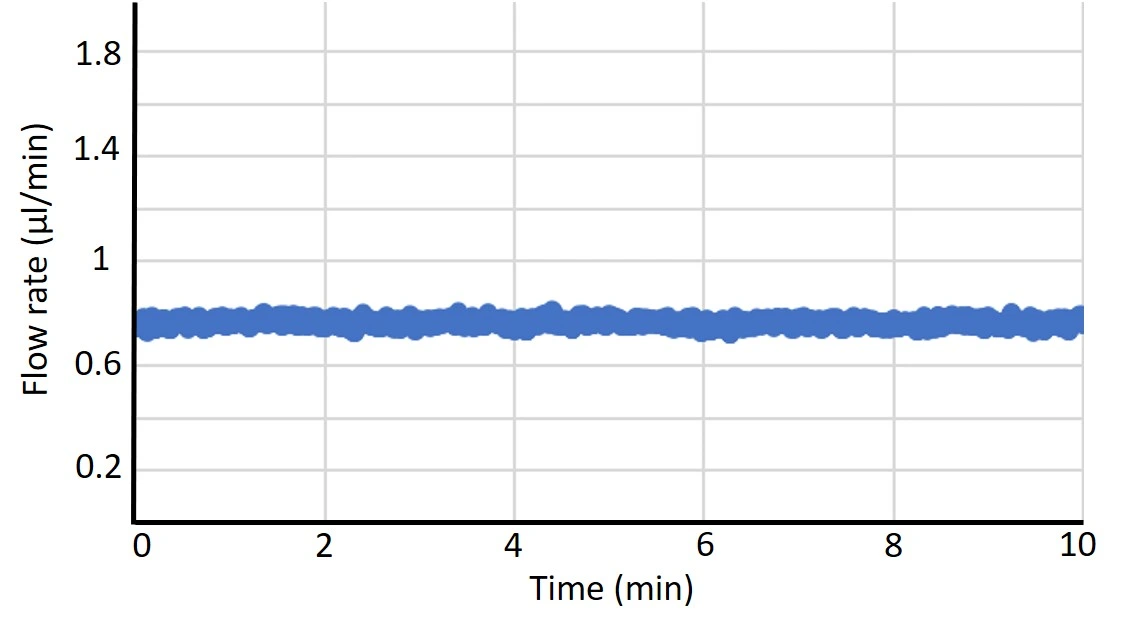
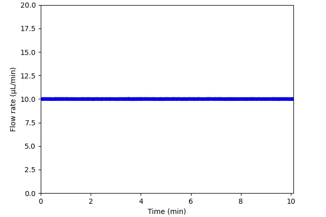
Figure 8: Comparison between flow profiles generated by a peristaltic pump, syringe pump, and pressure pump. Flow was measured by Galileo flow sensor.
Gear microfluidic pump
Pump flow profile: Steady, near-constant flow
Working principle: Microfluidic gear pumps consist of two or more gears that rotate against each other inside a tightly fitted housing. As the gears rotate, fluid gets trapped between the teeth of the gears and the housing, moving it from the pump inlet to the outlet.
Characteristics/Considerations:
- Smooth, low-pulsation flow.
- High precision and fast response to flow control.
- Steady flow even when the system encounters variations in backpressure or fluid resistance.
- Suitable for medium to high-viscosity fluids.
- The flow rate can be adjusted by changing the speed of the gears’ rotation.
- Not suitable for low-viscosity fluids.
- Limited flexibility in adjusting the volume of displaced fluid per revolution, which depends on the design of the gears.
Applications:
- Microreactors and for precise recirculation of drugs in medical devices.
- Microfluidic PCR (Polymerase Chain Reaction) and chromatography, that require low-pulsation, and constant flow [8].
An example of a gear pump is the micro annular pump developed by HNP Mikrosysteme. It consists of inner and outer gears assembled within the pump casing. When the inner gear is rotated, the outer gear is turned in the same direction. This pump’s plus is that the tight tolerances between the gears prevent liquid from leaking out on the discharge side, and the incremental gear rotation makes it easy to control the amount of displaced liquid.
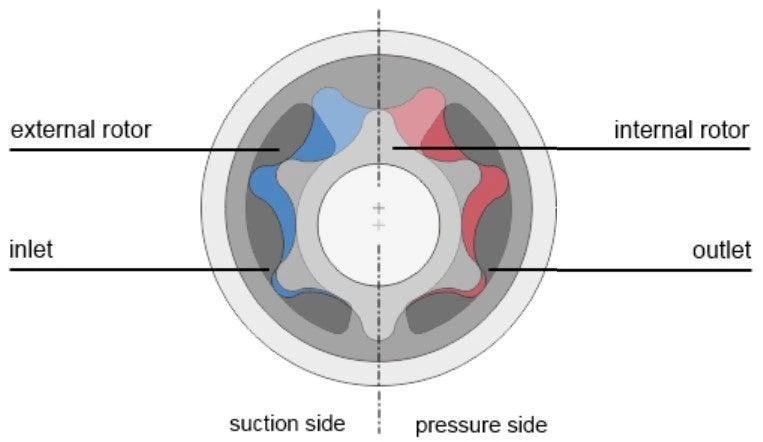
Figure 9: Principal components of a gear pump. (Image taken from Darwin Microfluidics website).
Electroosmotic microfluidic pump
Pump flow profile: Constant and pulseless flow, or tunable flow controlled by an electric field
Working principle: Electroosmotic pumps move fluids through microchannels by applying an electric field, generating flow due to the movement of ions.
Characteristics/Considerations:
- No moving parts, leading to minimal mechanical wear and tear.
- Fine control over very small (nL to pL) volumes.
- Sensitive to changes in fluid properties like pH, ionic strength, and channel surface conditions.
- Limited to polar and conductive fluids.
Applications:
- Single-cell genomics or proteomics, where small sample volumes must be precisely controlled and analyzed.
- Electrophoresis and capillary electrophoresis systems for separating biomolecules or ionic species based on size and charge.
- Affinity chromatography for protein or peptide separation and purification [9].
Centrifugal microfluidic pump
Pump flow profile: Centrifugal, steady, pulseless flow.
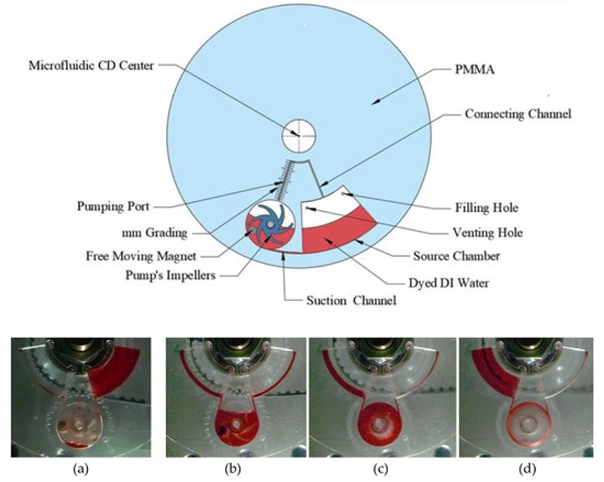
Working principle: Centrifugal pumps drive fluid flow using the rotational force applied to a microfluidic disk or platform. Fluids are pushed radially outward as the platform spins.
Characteristics/Considerations:
- Simple and can control multiple fluids in parallel.
- No external tubing or pumps required.
- Flow is continuous with the forward and backward fluid movement to the different compartments.
- Limited to applications on rotating platforms.
- Flow rate depends on rotational speed and platform design.
Applications:
- Point-of-care diagnostics, sample preparation, rapid mixing, and multiplexed assays in disk-based microfluidic platforms [11].
Other microfluidic pump mechanisms
Most microfluidic pumps are based on a piezoelectric mechanism or proportional valves.
Piezoelectric mechanism
A piezoelectric mechanism is based on the inverse piezoelectric effect, where an applied electric field causes a piezoelectric material to deform. This deformation drives a diaphragm within the pump, creating air or liquid compression that pushes the fluid through the pump chamber.
Characteristics:
- Very fine control over fluid volumes and flow rates by modulating the frequency and voltage of the applied electric signal.
- Fast response time due to the direct actuation mechanism.
- Often binary (fully open/close).
The MIC has 2 micropumps that function using pneumatic piezoelectric technology. Our Caterpillar pressure pump is based on a pneumatic piezoelectric micropump with air compression.
Our mini pump uses a pneumatic piezoelectric micropump with liquid compression.
Proportional valves
Proportional valves operate based on electromagnetic principles. When current passes through a solenoid actuator, the actuator generates a magnetic field, which moves the valves and pulls them against the force of the return mechanism. The valve opening adjusts continuously, providing a proportional flow rate based on the input. Proportional valves allow for precise, continuous fluid flow control, unlike binary valves that are open or closed.
Characteristics:
- Provide a broad range of continuous flow rates
- Precision depends on the resolution of the proportional actuator, but they may not achieve the same fine granularity as piezoelectric valves in certain applications.
- Slower response times compared to piezoelectric valves because of the mechanical movement of components.
- Better for applications where steady flow adjustments are needed over time.
Our cell culture pressure pump is based on proportional valves.
Some pumps are based on piezo-controlled proportional valves (eg. Hoerbiger) combining both mechanisms.
Microfluidic pump flow profile summary
|
Pump system |
Flow profile |
Flow rate |
Flow rate control |
Volume capacity |
Flow continuity |
|
Capillary-driven |
Passive |
Suitable for low flow rates |
Slow, self-driven by surface tension |
Not limited by volumes |
Continuous flow without interruptions |
|
Hydrostatic pressure |
Laminar |
Suitable for low flow rates |
None to limited; Can be controlled using a programmable rocking platform. |
Limited by reservoir height, requires refilling |
Disrupted when adjusting reservoir height or refilling reservoirs |
|
Syringe pump |
Oscillating, pulsatility depends on the pump |
Suitable for low flow rates |
Precise, controlled by the pump. |
Limited by syringe volume, requires refilling |
Disrupted when pull/push transition or when syringe empties |
|
Peristaltic pump |
Pulsatile, can be reduced with a dampener |
Not suitable for low flow rates |
Moderate, controlled by the pump and tubing selection. |
Limited by the volume of the reservoirs * |
Continuous flow without interruptions |
|
Pressure pump |
Highly stable profile; Variety of flows possible: pulsatile, steady, stepwise, custom |
Suitable for both low and high flow rates |
Very precise; Uses a flow sensor feedback loop |
Limited by the volume of the reservoirs ** |
Continuous flow, can be disrupted when refilling reservoirs |
|
Gear pump |
Smooth, near-constant |
Suitable for low flow rates |
Precise, controlled by the gears design |
Limited by the volume of the reservoirs |
Continuous flow without interruptions |
|
Electroosmotic pump |
Constant, pulseless |
Suitable for low flow rates |
Steady, controlled by an electric field |
Limited by the volume of the reservoirs |
Continuous flow, can be disrupted when refilling reservoirs |
|
Centrifugal pump |
Centrifugal, pulseless |
Suitable for high flow rates |
Radial, depends on rotational speed |
Not limited by volumes |
Continuous flow forward and backward without interruptions |
*Infinite volume looping in a recirculation setup with one reservoir
**Infinite volume looping in a recirculation setup with two reservoirs and an additional valve system for unidirectional flow
References
- Hsieh, H.-J., et al., Shear-induced endothelial mechanotransduction: the interplay between reactive oxygen species (ROS) and nitric oxide (NO) and the pathophysiological implications. Journal of Biomedical Science, 2014. 21(1): p. 3.
- Mérian, T., et al., Development and surface characterization of an electrowetting valve for capillary-driven microfluidics. Colloids and Surfaces A: Physicochemical and Engineering Aspects, 2012. 414: p. 251-258.
- Khamcharoen, W., et al., Capillary-driven microfluidic device integrating recombinase polymerase amplification for human papillomavirus detection. Sensors and Actuators B: Chemical, 2024. 401: p. 135016.
- Makhinia, A., et al., On-Demand Inkjet Printed Hydrophilic Coatings for Flow Control in 3D-Printed Microfluidic Devices Embedded with Organic Electrochemical Transistors. Advanced Materials Technologies, 2023. 8(15): p. 2300127.
- Haque, M.E., et al., Effects of syringe pump fluctuations on cell-free layer in hydrodynamic separation microfluidic devices. Physics of Fluids, 2021. 33(7).
- Behrens, M.R., et al., Open-source, 3D-printed Peristaltic Pumps for Small Volume Point-of-Care Liquid Handling. Scientific Reports, 2020. 10(1): p. 1543.
- Sullender, C.T., et al., Using pressure-driven flow systems to evaluate laser speckle contrast imaging. Journal of Biomedical Optics, 2022. 28.
- Alam, M.N.H.Z., et al., Design and fabrication of a 3D printed miniature pump for integrated microfluidic applications. International Journal of Precision Engineering and Manufacturing, 2017. 18: p. 1287-1296.
- Wang, X., et al., Electroosmotic pumps and their applications in microfluidic systems. Microfluid Nanofluidics, 2009. 6(2): p. 145.
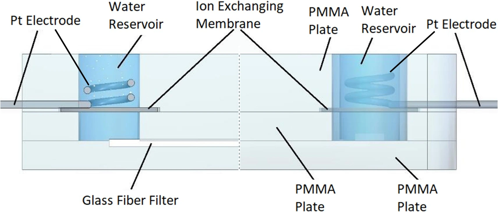
- Ecker, R., et al., Microfluidic High-Power Electroosmotic Pumps Based on Glass Fiber Filters. IEEE Sensors Letters, 2024. 8(9): p. 1-4.
- Al-Halhouli, A.a., et al., Development of Active Centrifugal Pump for Microfluidic CD Platforms. Micromachines, 2020. 11(2): p. 140.


This review was written by Celeste Chidiac, PhD.
Published in December 2024.
Contact: Partnership[at]microfluidic.fr

Check the other Reviews
FAQ - Microfluidic pump flow profiles: a comparative review
Just what is meant by the term flow profile in microfluidics?
The time-trace of your flow rate and the shear stress that is exerted upon cells or reagents. The profile with t being steady is called a steady profile; the profile with t being in cycles is called a pulsatile profile (also called reciprocating profile); the profile with t varying (disturbed) is called an irregular profile (disturbed/oscillatory profile). In practice, the majority of biological assays target steady (to achieve homeostasis) or softly pulsatile (to replicate physiology).
Under what circumstances should I use capillary or hydrostatic flow rather than an active pump?
You need maximum simplicity, noise-free functioning, and very low, constant flow with no electronics. Capillary flow is self-driven by surface tension and channel wetting; therefore, it is ideal for disposable tests or paper-based equipment. Hydrostatic flow relies on height differences between reservoirs. This is the reality of trade-offs: once initiated, it is difficult to maintain limited control; the flow rate varies over time as the head height changes; and manual operations (refilling or relocating reservoirs) temporarily disrupt the flow.
Syringe pump, peristaltic pump, or pressure controller- what is the difference in their real use flow profiles?
-Syringe pumps: the flow should be constant, but you will observe interruptions at the change of the syringes and during push-withdraw transitions. Strict uL/min-to-mL/min dosing Is Good, with an accuracy of a few tens of per cent on quality units.
-Peristaltic pumps: pulsatile due to roller compression; long-run and hands-off operation, but flow rates (less than 1 uL/min) are difficult to achieve, and calibration issues occur.
-Pressure pumps: you have control over pressure at the reservoir and can produce a variety of profiles, steady, stepwise, or pulsatile, particularly when you complete the loop by adding a flow sensor. Response to setpoint changes is quick.
What is the most suitable choice in terms of a really stable, low-noise steady flow?
Dynamic pressure-driven systems with a suitable flow sensor and feedback are the strongest direction toward a flat profile over hours. Syringe pumps follow (they are extremely stable at the time of one push), yet you have to design around swapping syringes. Peristaltic pumps may be dampened or tube-planed, but the remaining ripple is typically not negligible to shear-sensitive readouts.
Can I do recirculation? Unidirectional or bidirectional?
-Peristaltic: a unidirectional recirculating flow, which has one loop and one reservoir to serve as an inlet and outlet.
-Pressure: normally two-directional unless you insert check valves, a rotary valve, or a 3/2 scheme of valves to arrange one-way perfusion.
-Syringe: can take infusion/withdrawal cycles, although there will be a small dead time and a kink in the profile at every reversal. When the biological component of your system concerns the direction of flow (most do), consider the valving at the start.
I need very small volumes (nL–pL) and zero moving parts – what fits?
Fueled by electricity rather than mechanical parts, these pumps deliver smooth flow when voltage remains constant, making them suitable for handling biological samples with accuracy. Still, their operation requires liquids that carry charge well, while shifts in acidity, ion levels, or material surfaces can significantly alter results.
My reagents are shear-sensitive or viscous. Does the pump choice matter?
Definitely, gear pumps are used to manage medium- to high-viscosity media with almost constant flow and rapid response, at the cost of being unable to handle extremely low-viscosity media. In shear-sensitive cells or proteins, peristaltic pumps isolate the fluid in a soft tube and are useful for long perfusions, though you will have to deal with pulsation. Pressure controllers and other compliant elements can strike a balance between the two requirements, should you also require tight dose control.
To what minimum flow is it practicable to go?
Regarding that, as a rule of thumb, syringe pumps and pressure controllers are known to operate in the uL/min range (down to the low single digits with appropriate channels and sensors). Peristaltic pumps are hard to control and unstable below about 1 uL/min. For sub-µL/min, the safer options are the pressure + sensor closed-loop method or the electroosmotic method.
What are normal ways of failure that destroy flow profiles – and how can I avoid them?
-Bubbles: they squeeze and transform a pressure step to a wet momentary state. Degas, prefill lines, and have bubble traps.
-Compliance: soft tubing is used, long and smooth, to smooth pulsation, but this damages response time, selectivity, and length and materials.
-Viscosity or temperature drift. Viscosity variations will cause a drift in flow at constant pressure, so that temperature can be monitored, or the loop should be closed on flow.
-Back-pressure surprises: monitors design
-Refill/transition events: schedule syringe volumes, use a running overlap, or use a reservoir/valve to prevent hard stops.
Can a pressure pump always be considered superior to a syringe pump?
Not always, going by the experiment. Syringe pumps are easy and precise when you need to program a simple, long, constant infusion at a fixed resistance. With flow feedback pressure, dynamism, quick response, or the ability to adapt to shifts in resistance, the dynamic profile or pressure will most likely be victorious. Pressure systems and valving are highly adjustable for long-term closed-loop recirculation perfusion.
What can be the position of centrifugal systems?
At low speeds, they are bright when parallelization and compactness are required – rotational distribution of multiple fluids without external pipes. The on-disk profile is constant and spinless when spin is set, but you can only use a rotating platform environment, and the flow will depend on the spin speed and disk structure.
So, how do I select without making it too complicated?
Sketch a quick matrix before buying anything:
-Profile needed: consistent, sometimes slightly pulsed, adjustable settings. What matters most is reliability with room for small changes when necessary.
-Flow rates range from picoliters to nanoliters per minute using electroosmotic methods. Sub-microliter flows occur under pressure-driven systems when sensors are involved. Microliter-to-milliliter volumes move at up to 1 mL/min via syringe or pressurized setups. Peristaltic and pressure mechanisms support continuous circulation over extended durations.
-Some samples react when exposed to stress. Others flow slowly like syrup. Certain types pose risks during handling. A few are too valuable to risk losing.
-Operations: Unidirectional or bidirectional; real-time flow reading required; resistance to maintenance.
When the two choices are equal, go with the one with native sensing/feedback; most headaches are eliminated once you can observe and control the actual flow.
Is it possible for MIC to assist in establishing one-way flow systems alongside continuous monitoring setups?
A Horizon Europe proposal is taking shape, focused on either organ-on-chip systems or droplet-based microfluidics. Whether including a niche SME adds real value remains unclear. One factor might be how well their expertise aligns with the technical demands. Sometimes, such partners bring practical insight that academic teams lack. Still, integration challenges can arise if goals aren’t fully aligned. The benefit likely depends on specific collaboration dynamics rather than just presence.
True enough. When assessors see proven collaborators who deliver practical solutions, impressions shift. MIC brings expertise in microfabrication, fluid dynamics, and device architecture – alongside reliable prototype timelines – not just that, shared work on procedures and hazard planning strengthens proposals. More than lab skills, it removes uncertainty from project pathways. From what we’ve seen, scoring tends to rise noticeably.