Integrated microfluidic liquid-phase extraction system
Author
Celeste Chidiac, PhD
Publication Date
Keywords
Liquid-liquid extraction
Membrane-based devices
automated approaches
two-phase microextraction
Need advice for your liquid-liquid extraction?
Your microfluidic SME partner for Horizon Europe
We take care of microfluidic engineering, work on valorization and optimize the proposal with you
How can we miniaturize batch liquid-phase extraction down to the scale of microchannels? How does microfluidics investigate the kinetics of the target solute? Find the answers to these questions in the following review.
Introduction
Microfluidic liquid-phase extraction is an application of batch separation that uses microfluidic technology to perform this process on a small scale within microchannels.
It offers several advantages over conventional batch separation methods due to the precise control of fluid flow, reduced reagent consumption, and automation capabilities. This technique is commonly employed for rare earth elements recovery in biomedical research and the chemical and pharmaceutical industries.
This review gives you a general overview of microfluidic liquid-phase extraction, its advantages and downsides, its different methods, and primary applications.
The concept of liquid-phase extraction
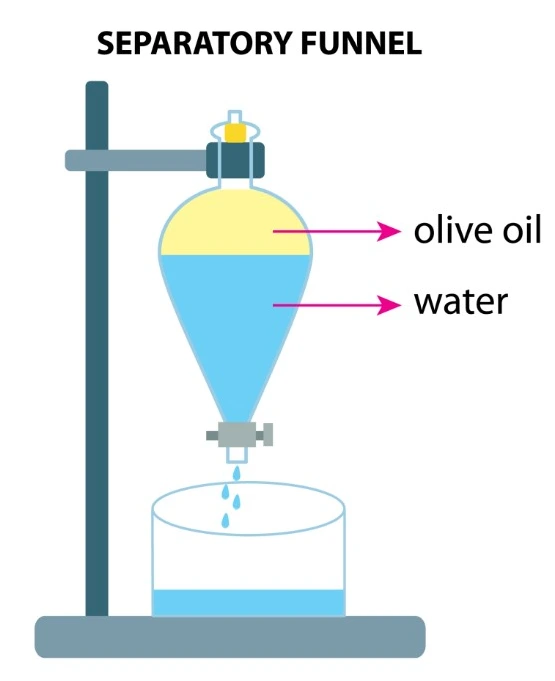
The liquid-phase extraction process (LPE), known as liquid-liquid extraction or solvent extraction, is a method to transfer and separate compounds from one liquid into another. It is based on compounds’ solubilities in two different immiscible phases: the aqueous phase, which contains the compounds of interest, and the organic solvent, which isolates the targeted elements based on their chemical affinity [1] (Figure 1).
The driving force of mass transfer relies on differences in chemical properties between the two phases, such as polarity and hydrophobicity/hydrophilicity [1]. Once the transfer is complete, all chemical components are in a more stable configuration.
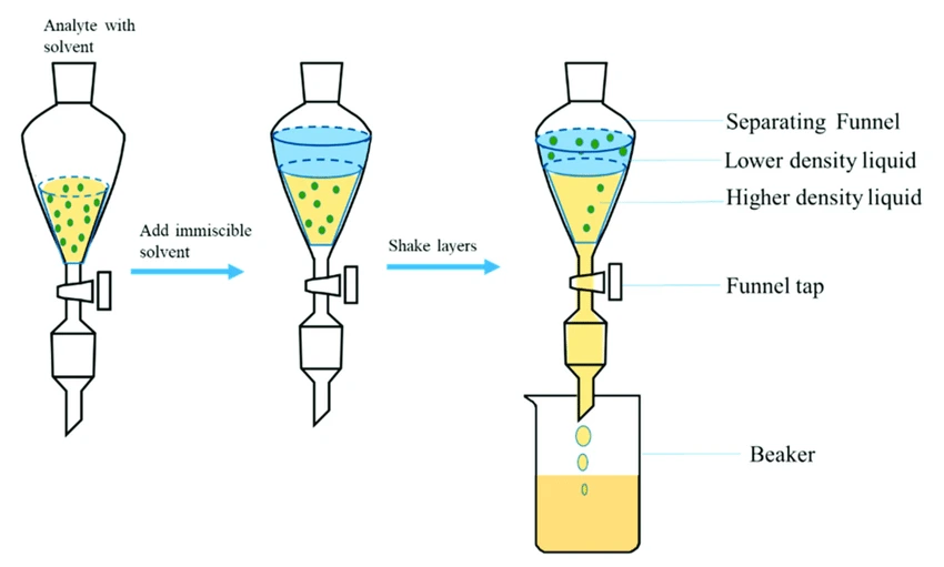
Conventional liquid-liquid extraction is performed using a separatory funnel. However, this process can be miniaturized down to the level of microchannels.
Using microfluidics for liquid-phase extraction
Microfluidics is both the science and application that can manipulate fluids at the scale of micrometers. It can integrate numerous microchannels on a single chip that fits in your hand. This technology allows you to save your precious sample, your time, and money.
Microfluidics have been integrated into solvent extraction, which makes this technique even more compelling.
Characteristics of microfluidic liquid-phase extraction
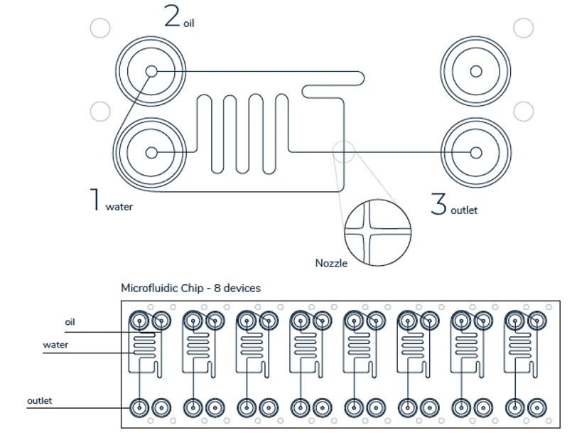
Microfluidic LPE performed in microchannels (Figure 2) follows the same basic principles as the batch process. It is also based on using two different phases, the feed and the extraction phases, that mix within microchannels (Figure 3). This process allows for efficient mass transfer and sorting of specific components based on their partitioning behavior between the two phases.
However, these phases are not necessarily immiscible but can be miscible and should be kept split after isolation. To avoid potential chemical interaction, the microfluidic device used for a specific reaction must be made of materials resistant to all the chemicals used. In addition, the devices must be leak-tight to a level well under the minimal flow rate [3].
The two phases can be precisely injected using a pressure-driven flow controller at a predefined ratio. Flow rates ranging from 100 µL/min to 100 mL/min or more can be accurately applied and controlled during the experiment.
As at the macroscopic scale, microfluidics separation is governed by distribution equilibria, reflecting the chemical affinity of a solute between the two phases. The drawing of the solute by the organic phase improves with a higher distribution equilibrium [3].
Liquid-liquid extraction is also characterized by residence time, contact time, and the contact area between the two phases. Contact time between fluids is when the two fluids are in contact, whereas residence time is the meantime that a solute spends in one of the phases.
A sufficiently well-defined contact area between the two phases, concerning sample volume, is required to keep reasonable contact times and, hence, for the separation to occur.
The longer the contact time is, the greater the amount of solute transferred until saturation of the extracting phase. However, a very long contact time induces the drawing of undesired molecules.
Thus, it is essential to define a precise residence time that will be enough to retrieve the targeted compounds and preserve the extraction yield.
This is possible by varying the microchannel dimensions or the flow rate in each phase to test the influence of different residence times on the process and investigate reaction kinetics.

As for every technology, advantages along with some downsides can be noted for microfluidic liquid-liquid extraction.
Advantages and downsides of microfluidic liquid-phase extraction
The miniaturization of extraction systems presents many advantages in comparison with macroscopic methods.
The diffusion distance of samples using the batch-wise system is a hundred times farther than continuous and droplet microfluidic devices (we discuss these devices further below).
Moreover, the total specific surface area of microfluidic devices is much larger than that of the batch device, which will result in an equilibrium state reached in just a few seconds (Figure 4).
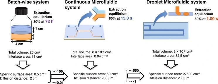
Additional advantages encompass a notable reduction in sample volume, the easiness of sample treatment procedures, and the possibility of membrane reuse.
Furthermore, incorporating membranes into such systems introduces an environmentally friendly dimension owing to their biodegradable and sustainable properties [5].
It allows the study of transfer kinetics, with fine control of hydrodynamic conditions, the absence of turbulence, and the reduction of molecular diffusion distances.
An automated and computer-controlled liquid-liquid extraction using a microfluidic platform integrated with necessary characterization methods is an excellent tool for obtaining structural, thermodynamic, and kinetic information about the studied process [3].
Thus, it is possible to determine the best operating point, a trade-off between the isolation selectivity and the number of retrieved elements for a given contact time [1]. The tool is also quite helpful in rapidly evaluating process stability and performance in new conditions.
In addition, in microfluidic liquid-phase extraction, a decantation step is unnecessary, and miscible liquids can be used, in contrast with batch liquid separation.
Moreover, the complete elimination of the organic solvent in aqueous two-phase and liquid-phase microextraction makes these systems powerful tools in sample treatment (we discuss it further below).
However, it is essential to note that this technique is not suitable for industrial scale but primarily for laboratory analyses due to the milli-volumes isolated. Nonetheless, microfluidic sample separation remains a remarkable data acquisition process, allowing the investigation of kinetic parameters with low product cost.
Let’s examine the microfluidic flow patterns used in the different LPE techniques.
Microfluidic liquid-phase extraction flow patterns
Laminar and segmented systems are the most used flow patterns, leading to parallel, droplet, and slug flow regimes, respectively. They significantly increase the interfacial exchange area between the phases, thus showing important extraction yields.
Laminar parallel fluid flow is usually obtained using Y-shaped inlet channels, with the two immiscible liquids being introduced concurrently and moving alongside until the exit (Figure 5 A-C). A third inlet/outlet can be introduced (Figure 5 D-F), increasing the interfacial area.
Using a laminar continuous flow pattern, separation attained chemical equilibria within seconds, whereas with conventional systems, several minutes are needed to achieve 96% yields [6].
Moreover, the phase separation occurs at the channel exit, allowing the recovery of the phase containing the targeted component. In contrast, laminar flow demands long residence times and, thus, long microchannels for complete sample retrieval [7].
In the segmented fluid flow of two immiscible liquids, the continuous phase of a liquid is segmented by discrete droplets of the distributed liquid phase. Segmented fluid flow displays slug or droplet flow regimes (Figure 5 I-K).
In this system, in addition to the increase in the interfacial exchange area, the internal recirculation events inside the drops and in the continuous phase allow very rapid interface renewal [7]. Segmented flow shows efficient separation rates achieved in just a few seconds [8].
Notably, convective transport, diffusion, and partition coefficients within the droplet or slug are parameters to consider [9].
A laminar flow pattern can be shifted to a segmented pattern by creating a perpendicular T-shape in the merging conformation of the inlets (Figure 5 G-H) or through flow-focusing geometries (Figure 5 I-K).
Shear forces and surface tensions between the aqueous and organic phases at the junction generate droplets or slugs, leading to flow instability and non-linearity. When this transition occurs, the surface-to-volume ratio considerably increases, leading to a higher mass transfer and a shorter residence time.
Thus, efficient retrieval equilibrium is achieved in a few seconds [7]. However, the most significant drawback of this pattern is the continuous phase separation at the outlets [10].
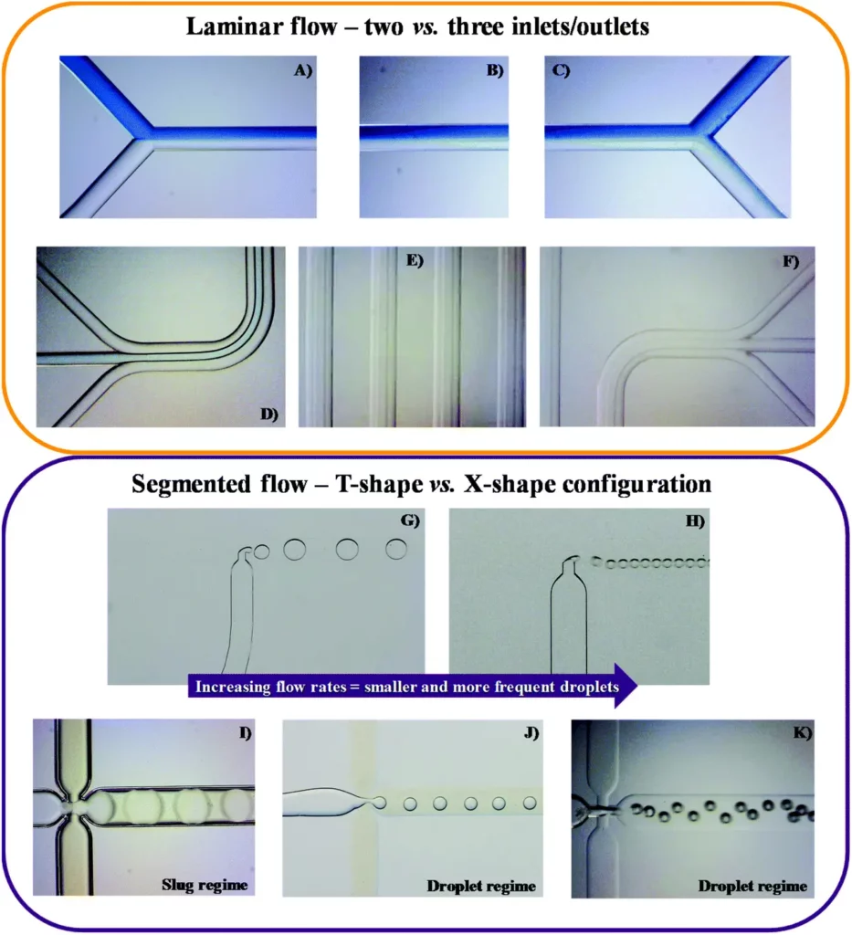
In conclusion, the transition to miniaturized processes resulted in higher transfer events, thus higher separation yields with shorter contact time, compared to macroscale isolation techniques. Researchers have improved mass transfer using fine emulsions or microfluidic geometries that induce high internal recirculation events.
The microfluidic geometries mentioned above are used in the different liquid-liquid extraction methods, with laminar flow being the most used one.
Microfluidic liquid-phase extraction methods
Several device methodologies have been developed, such as discrete microfluidics, guide-structure devices, membrane-based devices, aqueous two-phase microextraction, and fully automated approaches.
Discrete microfluidics
It primarily involves the use of slug flow or droplet flow regimes. In this setup, separation occurs within a single channel where flows are categorized into a slug or droplet flow, and mixing is an essential factor (Figure 6) [3].
Another critical requirement is to keep aqueous and organic droplets apart after isolation, stopping the process and contributing to proper post-experimental analysis.
Droplet abstraction can be done using finely tuned orifices to remove the solvent phase by capillary forces [11] or by leading the mixed flow through a separator device composed of two channels sandwiching a hydrophobic membrane [12].
The latter approach involves the application of significant backpressure on the outlet side, either by employing extended tubing or by utilizing a pressurized sample vial. Consequently, this forces the organic phase to pass through the hydrophobic membrane while the aqueous phase proceeds into the sample vial.
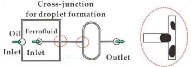
Guide-structure devices
This type of microfluidic system includes various channels or structures designed to direct and control fluid flow precisely on a microscale.
These devices are based on the principle of interfacial tension that prevents phases from mixing. Upon contact, the aqueous and organic phases tend to form an emulsion. Therefore, introducing geometric barriers becomes imperative to avoid emulsification [3].
Laminar flow patterns (Figure 7) can prevent such mixing or mixing and react fluids in controlled environments. Laminar patterns have the advantage over droplet-based patterns to allow simultaneous phase separation at the exit of the microfluidic device [7].
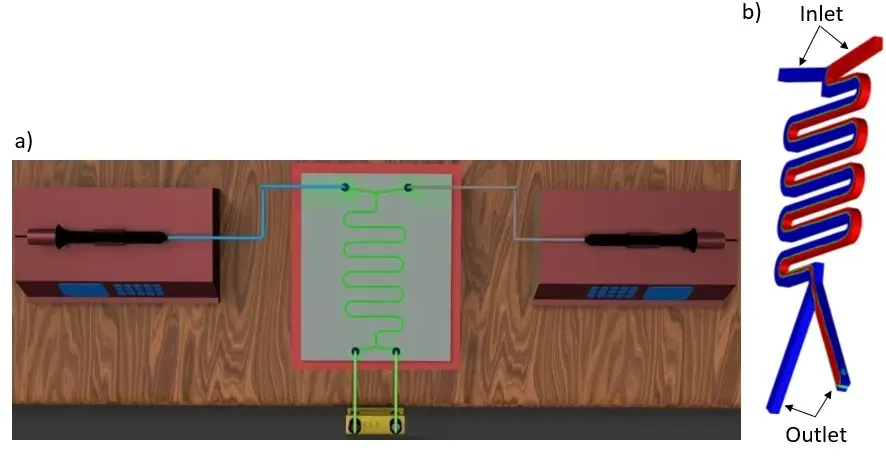
Guide-structure and discrete microfluidics have significant limitations due to the instability of flow patterns, which results in low capacity and productivity. Introducing a membrane in the extraction channel is a solution to stabilize the immiscible streams [7].
Membrane-based devices
It refers to a microfluidic device that uses a porous or semi-permeable membrane to facilitate the separation of aqueous and organic channels in a controlled and efficient manner (Figure 8).
A microfluidic cartridge with a permeable polymer membrane is introduced between two glass or polymer plates containing milled channels and microfluidic interfaces [16].
Before the organic phase, the aqueous phase should be introduced to prevent the organic liquid from leaking into the aqueous channel. No leak from the aqueous channel to the organic one can happen because of the hydrophobicity of the membrane [1].
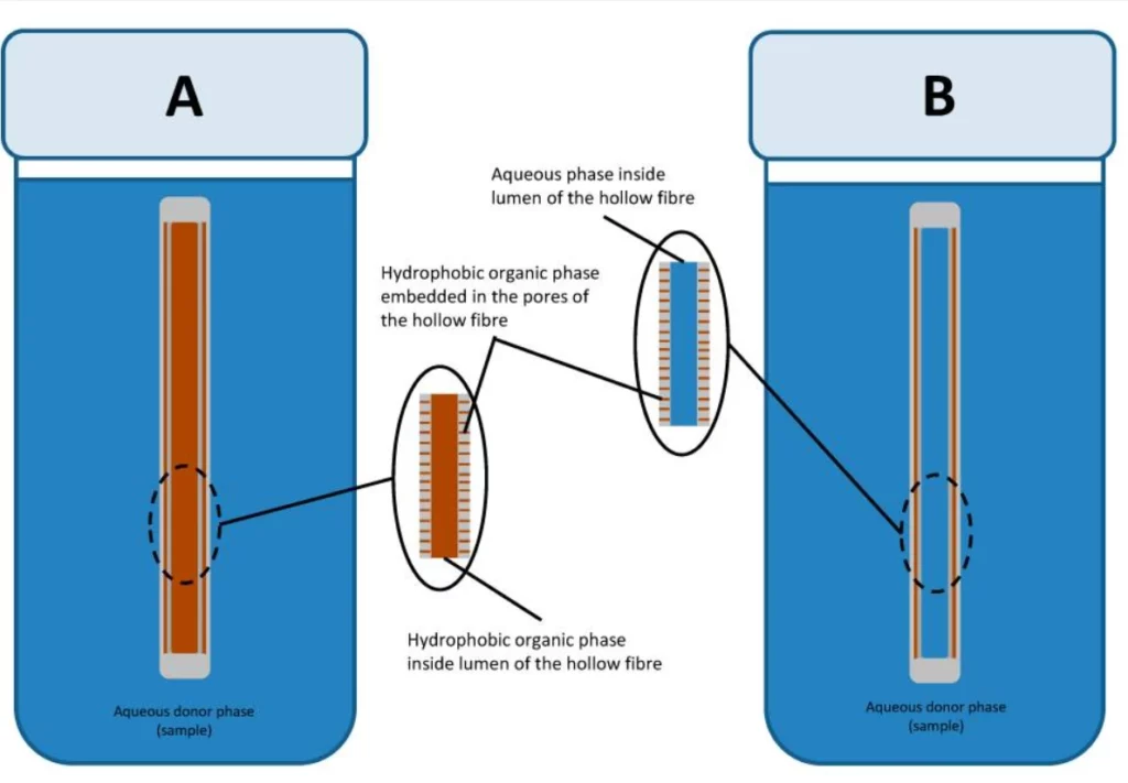
Liquid-phase microextraction (LPME) is a miniaturized version of the classical technique with minimal use of solvents. Analytes are retrieved through a supported liquid membrane embedded in the pores of solid support [17].
In this setup, the hydrophobic membrane is soaked into the organic phase, and both the channels above and below are filled with the aqueous phase. This technique is intended to isolate hydrophobic analytes from aqueous samples (Figure 9).
It’s essential to carefully adjust the chemical potential of both aqueous phases to facilitate the target species’ retrieval and subsequent re-retrieval.
The primary objective of this technique is to reduce the use of hazardous organic solvents and to concentrate analytes into a microliter volume, which can be injected and analyzed directly by liquid or gas chromatography [18, 19].
Aqueous two-phase microextraction
It is another technique that does not use organic solvents and allows the concentration of analytes in a small volume. This method is beneficial for isolating hydrophilic compounds from aqueous samples.
Two immiscible aqueous phases of polymers, an inorganic and a polymer salt, are used. The sample containing the analytes of interest is introduced into one of the aqueous phases, and then analytes are partitioned based on their solubility and chemical properties. After equilibration, the aqueous layers remain separate [7].
Fully automated microfluidic approaches
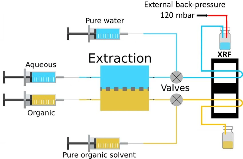
In an ideal microfluidic liquid-phase extraction setup, it is beneficial to systematically and automatically control temperature, concentrations, flow rate, and mixing ratio. However, achieving accurate control and assessment of these parameters is challenging.
Issues such as unstable flows or pressure drops can be addressed by implementing precise flow control systems, using shorter tubing, optimizing device geometries, and incorporating flow sensors.
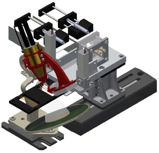
A platform with automated valves can screen the best extractant while dispensing many extractant solutions (Figure 10).
A simple microfluidic device that controls reagent concentration and dissolution was designed and termed as a “self-coalescent module” [21].
It is based on the capillary flow phenomenon, where a confined liquid with a stretched air-liquid interface is compelled to rejoin itself within a microchannel. This approach allows multiple reagent reconstitution with minimal dispersion.
The different liquid-liquid extraction methods we have seen above can be applied in various fields. So, let’s look at the diverse applications in the following section.
Microfluidic liquid-phase extraction applications
Integrating microfluidics into liquid-liquid extraction made this technique compelling for applications such as recovering rare earth elements, biomedical research, and the chemical and pharmaceutical industries.
Rare earth element recovery
Rare earth elements (REEs) encompass a group of metals with similar characteristics, comprising scandium, yttrium, and the entire lanthanide series. REEs are commonly mined as by-products of other materials and can be found in some hard rock deposits, acid mine drainages, and wastewater [22].
A leaching process uses one or more acid reagents on the crushed ores to obtain REEs. Afterward, the leach solutions are subject to a separation step. Liquid-liquid extraction is the most used process for isolating REEs from different sources. It brings the aqueous phase of the leach solution in contact with an organic phase containing one or more separating agents [23].
However, this technique uses large amounts of toxic and flammable solvents that are dangerous to human health and the environment [23]. One possible solution is using ionic liquids as alternative diluents or isolating solvents [24].
Biomedical research
A rapid and highly efficient approach using laminar flow was designed to identify and quantify bacterial pathogens. It is based on a microfluidic device composed of microwell arrays that selectively isolate and purify DNA and RNA of both Gram-positive and harmful bacteria.
After cellular lysis, biomolecules, including cellular debris and proteins, partition into the organic phase, while nucleic acids remain in the aqueous phase (Figure 11).
The study’s findings demonstrated that it is possible to control the partitioning of nucleic acids between organic and aqueous phases through precise adjustments of flow rates and by modulating the pH of the organic phase [25, 26].
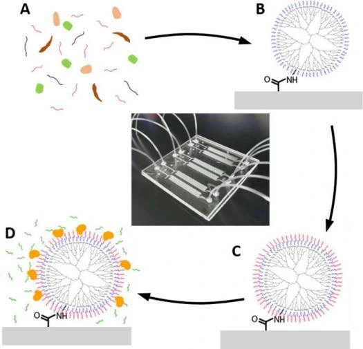
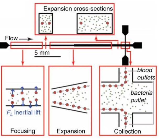
Microfluidic was combined with a buffer system containing electrolytes with different electrophoretic mobility. This method was used to isolate DNA from lysed blood samples and served, for example, to identify severe sepsis patients at high risk of death [27]. A massive processing straight channel expansion device was developed to sort red blood cells and bacteria based on their size difference [28] (Figure 12).
Chemical industry
Liquid-phase extraction is used for the production or isolation of bioactive compounds, the recovery of chemicals from waste streams, and the pre-concentration of compounds.
For example, the production of polyvinyl alcohol microparticles was done by a selective retrieval of aqueous polymer solution droplets coupled with microfluidics. Initial polymer solution concentration influenced the process, especially final particle size and isolation times [29].
The substantial quantities of biowaste and the surge of the ecological crisis led to research towards developing innovative products. Numerous bulk chemicals are manufactured through chemical alteration or fermentation of leftover materials, like starch or D-glucose sourced from biowaste [30].
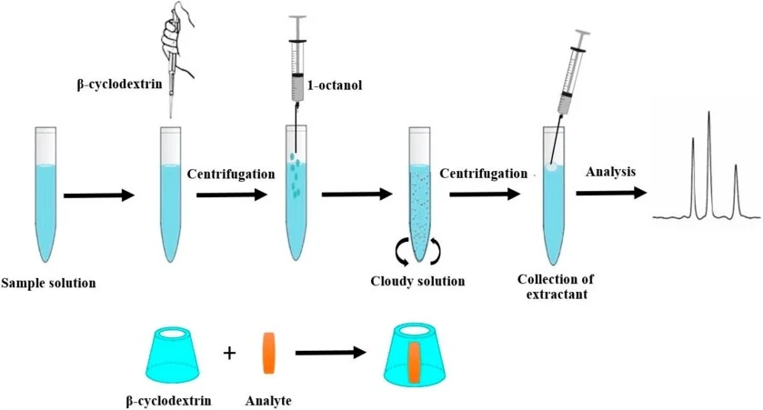
Contaminants in food, water, and environmental samples are usually found in trace concentrations. Thus, it is imperative to pre-concentrate these elements before instrumental detection. Miniaturized pre-concentration techniques, such as liquid phase microextraction, showed exciting results as they have low cost and relatively high extraction recoveries [31] (Figure 13).
Pharmaceutical industry
Liquid-phase extraction is commonly used to abstract and purify active pharmaceutical ingredients and isolate natural products from plant extracts.
Potential genotoxic impurities are one example of compounds in bulk drugs related to carcinogenic and mutagenic properties. Liquid-liquid microextraction was used to identify these compounds as part of the quality control process of pharmaceutical products [33].
Aqueous two-phase microextraction using bromide ionic liquids was studied to isolate saponins from Panax Ginseng. It resulted in a phase behavior with water where saponins were more soluble and highly retrieved [34].
Other two-phase separation methods are used to sort solid or gas samples from liquid. We will now look at these methods, mainly solid-liquid and gas-liquid extractions.
Further extraction methods
Solid-liquid extraction
Solid-liquid extraction is a prominent technique for the preparation of solid samples. It is based on the penetration of the extractant into the solid matrix, the exchange of thermic and mechanical energy with the surroundings, and the system’s progress toward a new equilibrium, where analytes are solubilized in the separating phase [35].
Solid-liquid extraction is commonly used for retrieving natural products from various plants. For example, phenolic compounds are abstracted from freeze-dried plant materials with different solvents, followed by column chromatography or solid-phase separation to remove unwanted substances [36, 37].
This technique has been known for its relatively low quantitative efficiency. However, integrating microfluidics into this technique reduced volumes and costs, decreased analysis time, and optimized efficiency.
Gas-liquid extraction
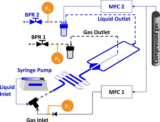
In microfluidic gas-liquid extraction, the liquid containing the target gas or volatile substance is introduced into a microchannel. The microscale dimensions of the channels enable efficient mass transfer and rapid mixing between the gas and liquid phases (Figure 14).
Microfluidics in gas-liquid two-phase systems can measure the gas dissolution rate, diffusion and transfer coefficient, and component concentration. For example, this was applied to characterizing CO2 fluidic behavior in CO2 capture and sequestration [38].
Conclusion-Towards fully automated extraction approaches
As we have seen, microfluidic liquid-phase extraction offers a powerful and versatile platform for performing efficient and controlled separations. It is a valuable tool in various scientific and industrial applications due to its efficiency, cost-effectiveness, and speed. Also, the possibility to eliminate the use of organic solvents is an eco-friendly alternative for high solvent-demanding applications.
Recent advances have rendered microfluidics technology more accessible and easier to use for different levels of expertise. Actual and future trends are heading towards fully automated and computer-controlled microfluidic approaches.
Depending on your experience level, a predesigned setup can help you perform your experiment in a plug-and-play style, with easy automation to inject your samples and monitor their flow rates accurately.
This review was written by Celeste Chidiac, PhD.
Published in October 2023.
Contact: Partnership[at]microfluidic.fr

References
- Olivier F, et al. Liquid-liquid extraction: thermodynamics-kinetics driven processes explored by microfluidics. Comptes Rendus Chimie. 2022;25:137-148.
- Targuma S, Njobeh P, and Ndungu P. Current Applications of Magnetic Nanomaterials for Extraction of Mycotoxins, Pesticides, and Pharmaceuticals in Food Commodities. Molecules. 2021;26:4284.
- Maurice A, Theisen J, and Gabriel J.C.P. Microfluidic lab-on-chip advances for liquid–liquid extraction process studies. Current Opinion in Colloid & Interface Science. 2020;46:20-35.
- Kurniawan Y, Sathuluri R.R, and Ohto K. Droplet Microfluidic Device for Rapid and Efficient Metals Separation Using Host-Guest Chemistry. IntechOpen. 2020;1-20.
- Santana H.S, et al. Review on microfluidic device applications for fluids separation and water treatment processes. SN Applied Sciences. 2020;2(3):395.
- Hellé G, et al. Toward numerical prototyping of labs-on-chip: modeling for liquid–liquid microfluidic devices for radionuclide extraction. Microfluidics and Nanofluidics. 2015;19(5):1245-1257.
- Vicente F.A, et al. Separation and purification of biomacromolecules based on microfluidics. Green Chemistry. 2020; 22(14):4391-4410.
- Hellé G, Mariet C, and Cote G. Liquid–liquid microflow patterns and mass transfer of radionuclides in the systems Eu(III)/HNO3/DMDBTDMA and U(VI)/HCl/Aliquat® 336. Microfluidics and Nanofluidics. 2014;17(6):1113-1128.
- Yu Y, et al. Design and application of a microfluidic device for protein crystallization using an evaporation-based crystallization technique. Journal of Applied Crystallography. 2012;45(1):53-60.
- Poulsen C.E, et al. A Microfluidic Platform for the Rapid Determination of Distribution Coefficients by Gravity-Assisted Droplet-Based Liquid–Liquid Extraction. Analytical Chemistry. 2015;87(12):6265-6270.
- Nichols K.P, et al. Toward mechanistic understanding of nuclear reprocessing chemistries by quantifying lanthanide solvent extraction kinetics via microfluidics with constant interfacial area and rapid mixing. J Am Chem Soc. 2011; 133(39):15721-15729.
- Kralj J.G, Sahoo H.R, and Jensen K.F. Integrated continuous microfluidic liquid–liquid extraction. Lab on a Chip. 2007;7(2):256-263.
- Zhu G.P, et al. Droplet Manipulation under a Magnetic Field: A Review. Biosensors (Basel). 2022;12(3).
- Jazayeri S.S, et al. Applying a microfluidic device to improve the Ca2+ separation performance of the liquid–liquid extraction process. Scientific Reports. 2022;12(1):21984.
- Amini Y, et al. Computational fluid dynamics simulation of two-phase flow patterns in a serpentine microfluidic device. Scientific Reports. 2023;13(1):9483.
- Theisen J, et al. Effects of porous media on extraction kinetics: Is the membrane really a limiting factor? Journal of Membrane Science. 2019;586: 318-325.
- Martín A, Santigosa E, and Ramos-Payán M. Green strategies using solvent-free biodegradable membranes in microfluidic devices. Liquid phase microextraction and electromembrane extraction. Analytica Chimica Acta. 2023;1274:341572.
- Wang X, Saridara C, and Mitra S. Microfluidic supported liquid membrane extraction. Analytica Chimica Acta. 2005;543(1):92-98.
- Dowlatshah S, et al. Microfluidic liquid-phase microextraction based on natural deep eutectic solvents immobilized in agarose membranes. Journal of Chromatography A. 2021;1657:462580.
- Madikizela L.M, et al. Application of Hollow Fibre-Liquid Phase Microextraction Technique for Isolation and Pre-Concentration of Pharmaceuticals in Water. Membranes (Basel). 2020;10(11).
- Gökçe O, et al. Self-coalescing flows in microfluidics for pulse-shaped delivery of reagents. Nature. 2019; 574(7777):228-232.
- Royer-Lavallée A, Neculita C, and Coudert L. Removal and potential recovery of rare earth elements from mine water. Journal of Industrial and Engineering Chemistry. 2020;89:47-57.
- Joshi D.R, and Adhikari N. An overview on common organic solvents and their toxicity. Journal of Pharmaceutical Research International. 2019;28(3):1-18.
- Singh S.K, and Savoy A.W. Ionic liquids synthesis and applications: An overview. Journal of Molecular Liquids. 2020;297:112038.
- Zhang R, et al. A microfluidic liquid phase nucleic acid purification chip to selectively isolate DNA or RNA from low copy/single bacterial cells in minute sample volume followed by direct on-chip quantitative PCR assay. Analytical Chemistry. 2013;85(3):1484-1491.
- Reinholt S.J, et al. Isolation and amplification of mRNA within a simple microfluidic lab on a chip. Analytical Chemistry. 2014;86(1):849-856.
- Yang J, et al. A microfluidic device for rapid quantification of cell-free DNA in patients with severe sepsis. Lab on a Chip. 2015;15(19):3925-3933.
- Mach A.J, and Di Carlo D. Continuous scalable blood filtration device using inertial microfluidics. Biotechnol Bioeng. 2010;107(2):302-11.
- Sharratt W.N, et al. Microfluidic solvent extraction of poly(vinyl alcohol) droplets: effect of polymer structure on particle and capsule formation. Soft Matter. 2018;14(22):4453-4463.
- Farrán A, et al. Green solvents in carbohydrate chemistry: from raw materials to fine chemicals. Chemical reviews. 2015;115(14):6811-6853.
- Musarurwa H, and Tavengwa N.T. Homogenous liquid-liquid micro-extraction of pollutants in complex matrices. Microchemical Journal. 2021;170:106750.
- Vichapong J, et al. β-Cyclodextrin Assisted Liquid–Liquid Microextraction Based on Solidification of the Floating Organic Droplets Method for Determination of Neonicotinoid Residues. Molecules. 2019;24:3954.
- Cui Y, et al. Dispersive liquid-liquid microextraction with high-performance liquid chromatography for the analysis of 1,4-benzodioxane-6-aldehyde in eliglustat tartrate active pharmaceutical ingredient Journal of Pharmaceutical and Biomedical Analysis. 2020;179:112988.
- He A, et al. Extraction of bioactive ginseng saponins using aqueous two-phase systems of ionic liquids and salts. Separation and Purification Technology. 2018;196:270-280.
- Priego-Capote F. Solid–liquid extraction techniques, in Analytical Sample Preparation With Nano- and Other High-Performance Materials. Elsevier. 2021;111-130.
- Xu C.C, et al. Advances in extraction and analysis of phenolic compounds from plant materials. Chinese Journal of Natural Medicines. 2017;15(10):721-731.
- Alara O.R, Abdurahman N.H, and Ukaegbu C.I. Extraction of phenolic compounds: A review Current Research in Food Science. 2021;4:200-214.
- Qiu J, et al. Microfluidics-based determination of diffusion coefficient for gas-liquid reaction system with hydrogen peroxide. Chemical Engineering Science. 2021;231:116248.
- Radhakrishnan A.N.P, et al. Hydrodynamic Characterization of Phase Separation in Devices with Microfabricated Capillaries. Langmuir. 2019;35(25): 8199-8209.
Check the other Reviews
FAQ - Integrated microfluidic liquid-phase extraction system
What is the basic theory of liquid-phase extraction?
Liquid-phase extraction (LPE) or liquid-liquid extraction or solvent extraction is a technique of separation that moves and isolates the compounds in one liquid into another, according to the difference in their chemical properties. Two phases that are immiscible are used in the process:
-A liquid phase in which the compounds of interest are contained,
-An organic solvent that isolates desired components selectively with respect to chemical affinity, polarity and hydrophobicity.
The driving force behind this urge to transfer chemical components between phases is the solubility difference between the two liquids till each phase attains a more stable condition.
What is the enhancement of microfluidics in extraction in the liquid phase?
The microfluidic technology scales the liquid phase extraction down to the micro scale in microchannels providing significant benefits that are not delivered by the conventional batch extraction:
-Diffusion produced results a hundred times further than batch systems.
-The total specific surface area was huge and it stabilized in seconds instead of minutes,
-Sample decreased to microliters or milliliters,
-Close control over the flow rates, mixing ratios and residence times,
-Computer controlled and automated operation combined with characterization techniques,
-Removal of decantation processes,
-Capability of utilizing miscible liquids in a specific arrangement.
The resulting gains allow determining the stability of processes fast, optimising operating conditions and exploring kinetic parameters with the use of minimum reagent amounts.
Which are the two major flight patterns?
Microfluidic extraction in liquid phase utilises two flow regimes:
-Laminar parallel flow: Immiscible liquids that are added via Y-shaped channels flow past each other until exiting, thereby providing homogeneous contact with each other and easy phase separation at the outlets. Other inlet channels have the potential of enhancing interfacial mileage. This is the type that has longer residence time and microchannels to extract fully but allows instant phase separation.
-Segmented flow: This is flow in which a liquid phase is divided into discrete droplets or slugs of another liquid phase to form slug or droplet flow regimes. This pattern creates recirculation processes within the system, which rapidly recycles interfaces with an effective separation process within seconds. Constant separation at outlets is the major challenge.
Which microfluidic forms of extraction exist?
There are five major methodologies that were developed:
-Droplet microfluidics or slug flow discrete microfluidics with special separation mechanisms,
-Guide structure apparatus with geometrical obstacles to emulsification and a laminar flow,
-Membrane-type devices that use hydrophobic membranes in between aqueous and organic channels so as to stabilize flow patterns,
-Microextraction of hydrophobic analytes in liquid phase, through the use of supported liquid membrane to concentrate aqueous samples,
-Two phase microextraction using aqueous phases of polymer immiscible aqueous phases In the absence of organic solvents.
-Full-automated systems combine accurate flow controls, thermal controls as well as automated screening.
The principals of Membrane-based extraction devices?
In membrane-based systems, the systems place a porous/ semi-permeable hydrophobic membrane in between two microfluidic channels:
-The membrane is impregnated with organic phase and the membrane has aqueous phases above and below,
-Before organic phase, aqueous phase should be added to avoid leakage,
-Hydrophobicity ensures that aqueous liquid does not enter into the organic channel,
-The stabilization of the immiscible streams provided by the membrane eliminates the instability of flow patterns that reduce the capacity,
-This setup allows the use of three phase systems to isolate hydrophobic analytes of aqueous samples.
The method reduces the use of hazardous solvents and focuses the analytes in the form of microliter volumes that can be analyzed directly using chromatographic methods.
What are the main benefits of microfluidic extraction in the liquid phase?
Key benefits include:
-Less consumption of samples in milliliters to microliters,
-Balance found within seconds as compared to minutes or hours,
-Improved transfer of mass by increased ratio of surface to volume,
-Accurate regulation of hydrodynamic conditions which allows kinetic investigations,
-Streamlined methods of sample treatment,
-Certain configurations of membrane reusability,
-When biodegradable membranes are employed or in removing organic solvents, eco-friendly operation.
-Automated analysis and control system integration.
-The major weakness is still scalability: microfluidic extraction is best suited to the volumes of laboratory analysis and not to the volumes of industrial production.
Which are applications in which microfluidic liquid-phase extraction is useful?
The technology is used in different areas:
-Recovery of the rare earth elements through the mining leachates and wastewater in the ionic liquids as the alternative solvents,
-Biomedical studies involving nucleic acid extraction of bacterial samples, DNA extraction of blood to diagnose sepsis and separation of blood cells size-wise,
-Reducing waste streams, recovering waste streams, and pre-concentration of trace contaminants in chemical industries like bioactive compound production, waste stream recovery, and pre-concentration of trace contaminants,
-Genotoxic impurities found in pharmaceuticals and natural products found in plant extracts such as saponins of Panax Ginseng are identified and separated by quality control methodologies.
What is the difference between liquid-phase microextraction and the conventional extraction?
A specialized and miniaturized technique is liquid-phase microextraction (LPME):
-Requires small amounts of organic solvents impregnated into solid support membranes,
-Elutes hydrophilic sample analytes present in aqueous samples,
-The results: concentrates the analyses into microliter amounts to inject directly into the instruments of analysis,
-Needs to pay close attention to the adjustment of chemical potentials in both aqueous phases,
-Offers more ecological substitute to traditional means that demand great amounts of solvents.
The method is especially useful in the analysis of trace contaminants in food and water, and other environmental samples where pre-concentration before instrumental analysis is mandatory.
What are emerging future trends of microfluidic extraction?
The way to go is complete automated and computer controlled platforms:
-Plumbed control of temperature, concentrations, flow rates and mixing ratios,
-Accurate flow regulation systems on pressure drops and flow instabilities,
-Automated valve screening optimum extractants,
-Self-coalescent modules based on capillary flow mechanisms of reagent reconstitution with low dispersion,
-Combination with real-time methods of analytical characterization,
-Higher accessibility by designing plug and play models of different levels of expertise.
-The innovations improve the structural, thermodynamic, and kinetic information acquisition without losing the main benefits of miniaturization and automation.

