
HORIZON-CL5-2027-03-D5-14: Combining onboard technologies for lower ship fuel consumption
Opening
15 December 2026
Deadline
Keywords
Ship energy efficiency
Onboard renewables
Wind assistance
Technology integration
Sea trials
Retrofits
ZEWT Partnership
heat recovery
Your microfluidic SME partner for Horizon Europe
We take care of microfluidic engineering, work on valorization and optimize the proposal with you
HORIZON-CL5-2027-03-D5-14: Onboard renewable energy solutions and energy saving measures to reduce the fuel consumption of ships by at least 55% (ZEWT Partnership)
How does wind assistance change the job of a ship’s heat-recovery system?
Wind assistance can reduce engine demand and leave less exhaust heat available for recovery. A technology that saves propulsion fuel therefore changes the operating conditions of another energy-saving device. Zhao and colleagues demonstrated this interaction in a simulated cargo-ship voyage: adding wind assistance reduced the contribution from an organic Rankine cycle, which converts waste heat into power. [1] The practical question for HORIZON-CL5-2027-03-D5-14 is how the combined installation behaves across the voyage, including periods when its components cannot deliver their standalone benefit.
Microfluidics Innovation Center (MIC) develops project-specific liquid-handling prototypes and flow-control systems. Its Flow Calibrator provides a reference for checking small-scale pumps and flow regulators. If a selected ship-energy solution needs a compatible small-flow test circuit, MIC could contribute as a consortium partner to its experimental validation. That laboratory role would support a defined subsystem within the maritime partners’ full-scale demonstration.
Download the MIC Horizon Europe 2026/2027 Calls Calendar:
Discover more!
HORIZON-CL5-2027-03-D5-14 call facts and participation conditions
When is the opening and the deadline and what are the conditions to participate?
- Topic: HORIZON-CL5-2027-03-D5-14, in the Mobility call and the destination Clean and competitive solutions for all transport modes.
- Opening: 15 December 2026. Deadline: 14 April 2027, 17:00 Brussels local time.
- Action: Innovation Action (IA), funded as a lump sum. The topic budget is €6.50 million, with around €6.50 million expected EU contribution per project and an indicative one project. Different requested amounts remain possible.
- Maturity: activities are expected to reach technology readiness level (TRL) 8 by completion and may start at any TRL.
The General Annexes normally require three independent beneficiaries in three different countries: at least one in an EU Member State and two others in different Member States or Associated Countries. The maximum IA funding rate is 70%, or up to 100% for non-profit legal entities; for lump sums, the rate is applied when fixing the amount.
Participation restrictions apply. This destination excludes entities established in China. The topic also excludes eligible-country entities directly or indirectly controlled by China or a China-established entity. Projects using satellite observation, positioning, navigation or timing services must use Copernicus and/or Galileo/EGNOS, while additional services are allowed. The granting authority may object to ownership transfers or exclusive licensing of results for up to four years after the action. The Cluster 5 work programme sets out the complete conditions.
Demonstrate the combined benefit at ship scale
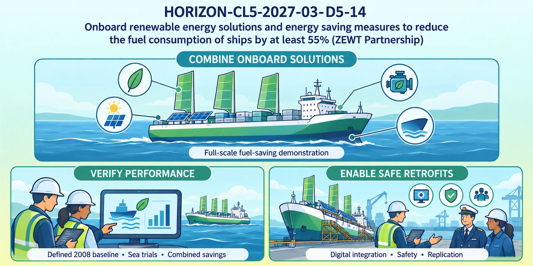
The central scope requirement is a full-scale demonstration reducing fuel consumption by at least 55% compared with 2008 levels. Proposals must explain the baseline for the retrofit or newbuild and its existing or expected operational profile. Fuel consumption, energy savings, greenhouse-gas (GHG) intensity and pollutant emissions need clearly distinguished indicators.
Candidate combinations include wind-assisted propulsion, electric or hybrid systems, hull improvements and air lubrication. Integration should address energy conversion, propulsion, onboard service loads and power systems while preserving safety and performance. Each technology needs an individual assessment alongside the combined result across different scenarios.
The expected outputs extend to verification methods, assessment criteria and sea-trial procedures, with standardised interfaces between efficiency verification and renewable-energy certification supporting FuelEU Maritime. Digital integration should build on existing energy-management solutions and connect with ship automation and class-certification processes.
Replication and retrofit design, cost-effectiveness and life-cycle assessment belong in the same plan. Assess air and water pollution and underwater noise, address data integrity and cybersecurity, and develop joint training for crews, ports and shore-side emergency services. The work should support retrofit uptake up to 2030 and the continued use of its outputs.
Design trials that reveal technology interactions
The following design recommendations turn the topic’s combined-performance objective into an interpretable demonstration.
- Fix the comparison. Define the vessel, route, speed, payload and operating profile represented by the 2008 baseline. Document how historical or modelled reference data relate to the demonstrator.
- Test combinations explicitly. Where safe and technically feasible, compare individual technologies and combined operation under matched conditions. Record environmental conditions and auxiliary consumption, including pumps, fans and rotor drives.
- Cover changing demand. Include cruising, manoeuvring and port operation, alongside relevant heating, cooling and service loads. Agree how periods of unavailable equipment enter the analysis.
- Define acceptance before trials. Specify measurement uncertainty, data exclusions, repeatability and the evidence required by the vessel operator and certification partners. Keep simulated predictions separate from sea-trial observations.
Heat recovery also requires decisions about where and when recovered energy is useful. Niknam and colleagues modelled an integrated system supplying power, heating and cooling over a 17-day vessel itinerary, with thermal storage supporting the recovery technologies. [2] This illustrates a design variable for the consortium: the operating schedule and connections between devices must be evaluated alongside their installed capacities.
Build the consortium around installation and operational interfaces
A HORIZON-CL5-2027-03-D5-14 credible consortium needs access to a suitable vessel and its operating data. Shipowners or operators, shipyards, naval architects and equipment suppliers should connect the proposed technology combination to installation space, structural constraints, maintenance and the ship’s service schedule.
Marine energy-system specialists can integrate propulsion, power and thermal loads. Automation and cybersecurity partners should define interfaces, data ownership, access controls and safe responses to lost or unreliable data. Classification and verification expertise should inform the evidence plan before equipment installation. These are recommended functions, rather than a prescribed consortium size or partner quota.
Training should address the actual combined installation and involve crews, ports and emergency services. Exploitation planning should cover retrofit downtime, maintenance costs, supplier support and the affordability of adoption for smaller shipping companies.
Proposals are expected to explain EU added value and strategic autonomy across the supply chain, including IP management and exploitation. The topic encourages priority for shipyards and equipment providers located or manufacturing in the EU and EEA. Funded projects are expected to report results for Zero Emission Waterborne Transport (ZEWT) partnership KPI monitoring.
A defined fluidic validation contribution from MIC
MIC could support a small-flow experimental task where a chosen thermal or auxiliary-energy subsystem requires controlled liquid delivery. The starting point should be a specified measurement problem, such as checking whether a laboratory pump delivers the intended flow during a sequence of operating conditions.
The Flow Calibrator benchmarks pumps and flow regulators and provides real-time feedback on flow behaviour. Its underlying flow-sensor technology received support through the completed Horizon Europe EIC Transition project GALILEO. The calibrator remains a non-commercialised research prototype; its public specifications identify beta status. A marine application would require its own compatibility and validation work.
Within MIC’s consortium-partner approach, a proposed contribution could produce a fluidic requirements specification, a controlled test setup and a subsystem validation report. The thermal-equipment partner would supply the relevant fluid, operating envelope and reference method. Maritime partners would establish how the laboratory result informs equipment integration and ship-level performance.
Fluid compatibility, temperature, pressure, flow range and measurement uncertainty need agreement before selecting hardware. The call’s TRL 8 objective applies to the project activities; it does not establish the readiness of this prototype for shipboard use. MIC’s participation would depend on a task that materially supports the chosen energy-saving combination.
The MIC already brings its expertise in microfluidics to Horizon Europe:
H2020-NMBP-TR-IND-2020

Microfluidic platform to study the interaction of cancer cells with lymphatic tissue
H2020-LC-GD-2020-3

Toxicology assessment of pharmaceutical products on a placenta-on-chip model

About the author

Céleste Chidiac, PhD
Scientific writer and digital marketing specialist
Céleste Chidiac holds a doctorate in neuroscience and molecular biology from the University of Strasbourg. Since joining the Microfluidics Innovation Center in 2023, she has combined scientific writing with website management. For MIC’s Horizon Europe topic pages, she draws on her research background to explain scientific challenges and clarify funding priorities. Her writing helps prospective applicants understand each topic’s scope, expected outcomes and research directions.
FAQ — Measuring and integrating ship energy-saving technologies
These questions examine component behaviour, experimental limits and evidence transfer when several technologies operate on the same vessel.
Why should a rotor sail’s electrical demand be included?
A powered rotor consumes electricity while producing aerodynamic thrust. Zhao and colleagues’ simulations show that increasing rotor operation can lower main-engine demand while raising generator demand. [1] Evaluate the net effect on the vessel’s fuel use, including the supply of that electricity, rather than reporting propulsion assistance alone.
Can one simulated voyage establish savings for every route?
No. Wind conditions, heading and engine loading change with the voyage. Zhao and colleagues identify route and weather dependence and omit rotor transverse-force effects from their simplified model. [1] Use such findings to design tests, then assess manoeuvrability and performance for the intended vessel and operating conditions.
What can thermal storage add to a heat-recovery installation?
Thermal storage can shift the use of recovered heat in time. Niknam and colleagues included storage alongside power and cooling technologies in their vessel-system optimisation. [2] Its value depends on the timing of available heat and demand; a proposed installation should also account for storage losses, mass, space and operating constraints.
How should two technologies claim credit for a shared saving?
Define the attribution method before comparing results. A combined-system saving may include an interaction that belongs to neither device in isolation. Report standalone contributions, the measured or modelled combined result and the allocation rule separately. This lets equipment suppliers assess their contribution without counting the same benefit twice.
What should happen when sea-trial measurements are missing?
Use a predefined data-quality rule. Flag the gap, retain its duration and operating context, and distinguish estimated values from observations. Assess whether missing periods could bias the comparison, for example if gaps cluster during difficult operating conditions. Repeating a test may be more defensible than filling an unrepresentative interval.
Does measuring liquid flow establish recovered thermal power?
No. Flow is one input to a thermal assessment. A single-phase liquid circuit also needs suitable temperature measurements and fluid-property data; a phase-changing system requires an appropriate enthalpy balance. Sensor placement, heat losses and transient energy storage affect the calculation. The thermal-system partner should define and validate that measurement model.
Why must the test fluid be specified before choosing a flow instrument?
Fluid properties and wetted-material compatibility affect the usable configuration and calibration. MIC’s Flow Calibrator specifications identify aqueous calibration and configuration-dependent operating ranges. A consortium should confirm suitability for its actual fluid and conditions before planning an experiment; the calibration should not be transferred to a different liquid without assessment.
Can MIC’s Flow Calibrator directly verify a ship’s total fuel saving?
No ship-level verification follows from the calibrator’s laboratory function. A compatible small-flow test can help characterise one subsystem. Total fuel-saving verification requires the vessel’s measurement plan, representative operating data and suitable reference instrumentation. Any transfer from a laboratory result to the ship model needs explicit assumptions and validation.
How can retrofit replication avoid repeating the entire development?
Separate reusable interfaces and test methods from vessel-specific engineering. Retain equipment requirements, data definitions, commissioning procedures and acceptance criteria, then reassess structure, space, stability, service loads and maintenance access for each vessel. Replication should preserve the evidence needed for safe integration while adapting the installation to its new context.
What makes a laboratory handover useful to maritime partners?
A useful handover identifies the tested hardware, fluid, operating envelope, protocol, reference method and uncertainty. Include failures and excluded conditions as well as successful runs. For an agreed MIC task, these records would let the equipment integrator judge which findings can inform design and which require further testing at equipment or vessel scale.
References
[1] Zhao, S., Pazouki, K. and Norman, R. Performance Evaluation of Combined Wind-Assisted Propulsion and Organic Rankine Cycle Systems in Ships. Journal of Marine Science and Engineering. 2025;13(7):1287. https://doi.org/10.3390/jmse13071287
[2] Niknam, P. H., Fisher, R., Ciappi, L. and Sciacovelli, A. Optimally integrated waste heat recovery through combined emerging thermal technologies: Modelling, optimization and assessment for onboard multi-energy systems. Applied Energy. 2024;366:123298. https://doi.org/10.1016/j.apenergy.2024.123298